Welcome: Jiangmen LEDER Lighting Co., Ltd.


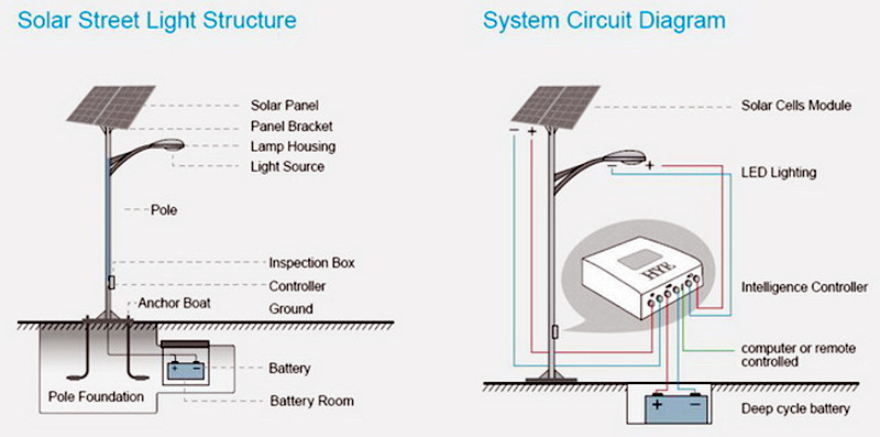
The article discusses the control and optimization of solar-powered street lights, focusing on various control principles and technologies employed in solar street lighting systems. It delves into the principles of solar tracking control, maximum power point tracking (MPPT) control for solar panels, and the overall control strategies for solar street lighting. Furthermore, the article explores the system structure of a solar LED street light that utilizes the STM32F101RXT6 microcontroller for efficient operation.
The principle of solar tracking control addresses the relatively low utilization rate of solar energy, which can be attributed to the low light-to-electricity conversion efficiency of solar cells and the inability of solar panels to track the sun in real time. The peak moment for solar radiation energy occurs around noon when the sun is due south. Consequently, many solar panels are fixed facing south, but this static orientation cannot continuously capture the maximum radiation energy.
Various active sun-tracking control methods exist, one of which is the use of light-sensitive sensors. This approach relies on the linear relationship between the open circuit voltage of photovoltaic modules and the corresponding radiant energy to track the sun's movement trajectory.
As the sun consistently moves from east to west, its trajectory changes slowly, and the change in the angle of elevation is typically within 10 degrees. Thus, there is no need to adjust the tilt angle of the solar panel, simplifying the mechanical adjustments required. Figure 7-40 illustrates the control flow chart for using a synchronous motor to adjust the solar panels to follow the sun's movement.
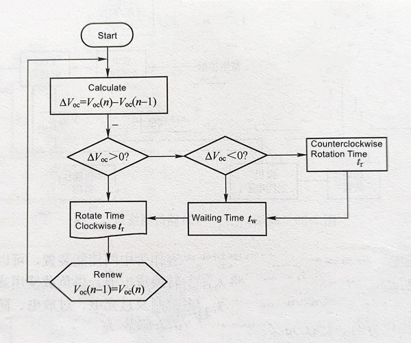
In Figure 7-40, Voc (n) and Voc (n-1) represent the current and previous open circuit voltage values, respectively, and ΔAVOC signifies the change in open circuit voltage. Since the sun moves from east to west during the day, the open circuit voltage can be adjusted by moving the solar panel clockwise by a unit angle per unit time (tr). This allows the solar panel to adapt to changes in the open circuit voltage and capture maximum solar energy. If ΔAVOC is less than zero (ΔAVOC < 0), the panel is rotated counterclockwise within the time interval tr, followed by a waiting period tw before moving clockwise again. If ΔAVOC is equal to zero (ΔAVOC = 0), it waits for tw time before starting the clockwise rotation. The waiting time tw is essential as it effectively reduces power consumption during rotation.
When the chosen unit rotation angle is 30 degrees, tr is 2 seconds, and tw is 30 seconds, and a solar panel tilt angle of 23 degrees is maintained, using a synchronous motor produced by Toshiba to control the solar panel's rotation, the active solar tracking system can increase the output power of fixed panels by 15%.
The photoresistors RL1 and RL2, along with resistors R1 to R4, form a light signal detection circuit. RL1 and RL2 are positioned in the photometric circle, symmetrically on both sides of a partition, as illustrated in Figure 7-42 (a). When the photometric circle directly faces the solar light (as shown in Figure 7-42 (b)), both RL1 and RL2 receive equal light intensity, resulting in equal resistance values. This leads to an output voltage of 0.5Vcc. If light is incident towards RL2 (as in Figure 7-42 (c)), RL2's resistance is less than RL1's, causing the output voltage at point A (VA) to be less than 0.5Vcc. When light is directed towards RL1 (as in Figure 7-42 (d)), VA exceeds 0.5Vcc.
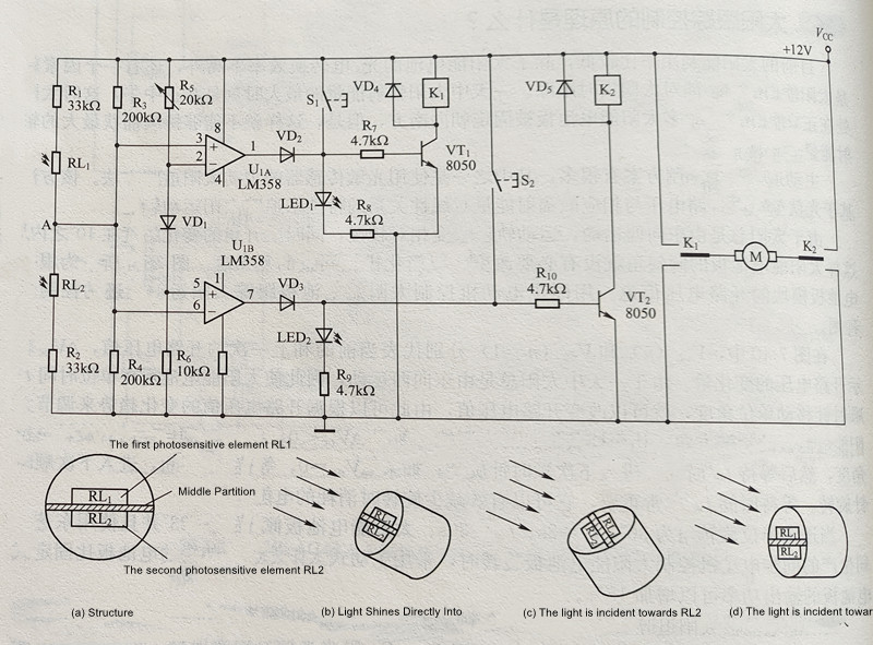
The control circuit further includes an LM358 (UiA/Ui), diode VD, and resistors R. These components form a direction recognition circuit. Due to the connection of diode VD, the reference voltage of UiA and UB differs by approximately 0.6V due to the PN junction voltage drop. By adjusting resistor R, the reference voltages can be set to appropriate levels, allowing comparators U1 and U2 to output high or low levels based on the light direction.
Transistors VT1, VT2, and relays K1 and K2 create the motor drive circuit. The potential at point A rises when light hits RL1 or RL2, enabling motor control in one direction or the other, depending on the specific light conditions.
Manual buttons (S1 and S2) are included for manual motor control, and LEDs (LED1 and LED2) serve as status indicators. The relays (K1 and K2) control the motor's forward and reverse rotation.
This control circuit can automatically track the sun or be manually operated to ensure optimal solar panel orientation for maximum energy capture.
The principle of Maximum Power Point Tracking (MPPT) control for solar panels is essential for efficiently harnessing solar energy. Solar cell output power depends not only on light intensity but also on temperature and load current. Solar cells have a specific Maximum Power Point (MPP) at a given temperature, and MPPT technology is used to ensure that the load characteristics of solar cells automatically adapt to changing weather conditions, allowing the system to maximize energy capture under varying sunlight conditions.
To achieve the highest energy efficiency from solar panels, a circuit must be designed to adapt to changing battery voltage and peak power voltage of the solar cells. This ensures that the solar panel operates at its maximum power output. Because the peak voltage of solar cells varies with temperature and solar radiation intensity, and the system may use batteries with different specifications (e.g., 12V or 24V), a circuit topology that can both boost and buck (step up and step down) the voltage is necessary. There are three primary circuit topologies capable of doing this: BUCK-BOOST converter, CuK converter, and SPEIC converter. Among these, the SPEIC converter is preferred because it maintains the same polarity for both input and output voltages, making it more convenient for system design.
Figure 7-43 illustrates the schematic diagram of an MCU-based SPEIC converter charging circuit subsystem.
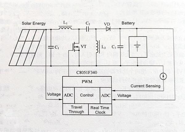
For the SPEIC converter shown in Figure 7-43, the transfer function (ignoring the voltage drop across VD) is expressed as follows:
VOUT = VIN[D / (1 - D)] - D
In this formula:
VIN represents the voltage at the peak power of the solar panel.
VOUT is the battery voltage.
D is the switch duty cycle.
The formula for calculating the inductance of inductors L1 and L2 is as follows:
L1 = L2 = VIN / △IL * FSW
In this formula, △IL represents the inductor ripple current (usually 20% of the maximum charging current), and FSW is the switching frequency (typically 100kHz).
Numerous MPPT control strategies exist, including the open circuit voltage method, constant voltage method, power differential method, numerical control matching method, disturbance observation method, incremental conductance method, fuzzy logic method, and artificial neural network method. Among these methods, the disturbance observation method stands out due to its low cost and high control accuracy.
The disturbance observation control method is a real-time MPPT algorithm that alters the working state of solar photovoltaic cells by introducing a controlled disturbance to the circuit. Simultaneously, it observes and calculates the actual output power of the solar panel, compares it with previous values, determines the next disturbance direction based on the comparison results, and finally stabilizes the solar panel's output near the maximum power point.
Traditional charging circuits charge the battery from solar cells through a diode. However, this approach is costly, with low solar energy utilization during charging and a lack of control over the charging process, leading to shortened battery life. Using a charging circuit with MPPT capability helps overcome these shortcomings associated with direct diode charging.
The principle of solar street light control involves the optimization of the system's design to ensure its long-term operation. System capacity can be optimized based on local geographical and meteorological conditions, as well as load requirements. However, even in the same location, the amount of solar radiation varies between seasons. For example, the average daily radiation in Harbin in June is nearly five times that in December. Solar energy generation is lower in winter compared to summer, but the demand for lighting is significantly higher in winter than in summer. This disparity makes it challenging to balance the surplus power generation in some months with the deficit in others.
To improve the utilization of power generated by the lighting system and address the issues arising from power shortages, an "on-demand lighting" power supply strategy can be implemented. This strategy involves switching control, which can be achieved through methods like Pulse Width Modulation (PWM) and programming to control brightness within specific time periods. For example, it can control the brightness during the first and second halves of the night, employ a single-sided road strategy where street lights on one side of the road are powered by the battery, while those on the other side are turned off. Another approach is a night light strategy, where lights are turned on in the first half of the night and then turned off, utilizing the battery for lighting only in the first half of the night. Additionally, a combination of solar power and AC mains power supply can be used. When solar energy cannot provide sufficient energy, the system switches to mains power supply.
The urban street lighting system has gone through a development process that includes manual control, automatic timing/photoelectric control, and computer program control. Utilizing computers for the automatic control of urban solar street light systems offers significant economic and social benefits. It helps improve the city's modern management level and results in savings in terms of manpower and resources.
The system structure of the solar LED street light composed of the STM32F101RXT6 microcontroller is depicted in Figure 7-44. This solution automatically detects ambient light to control the streetlights' operation, ensuring optimal solar panel efficiency. Additionally, it provides functions such as battery status output and user-programmable LED working time.
Figure 7-44 Structural diagram of solar LED street light based on microcontroller STM21F101RXT6
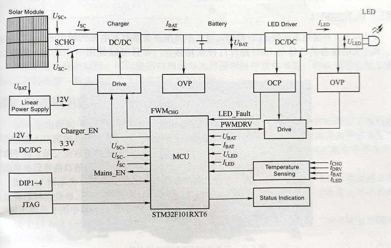
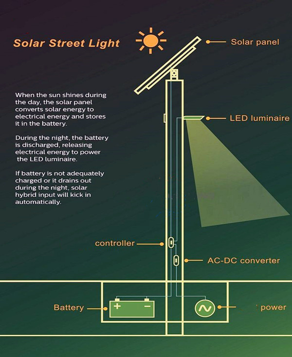
In this system, the DC current generated by the solar panel under sunlight is directed to the controller for battery charging. The battery charges during the day and supplies energy to the LED during the night, all under the control of the microcontroller. In cases of continuous cloudy days or insufficient battery power, the controller sends a control signal to activate an external mains power supply system to ensure the LED's normal operation. The external mains power supply acts as a backup energy source and is only utilized when the battery power is insufficient. The battery primarily charges through solar energy to maximize its utilization.
When the solar panel voltage is received, it is initially connected to the DC/DC converter (battery charging circuit) through a switching MOS tube SCHG. This converter's output is linked to both ends of the battery, with a fuse in between (in the actual circuit). The addition of SCHG serves two purposes: preventing reverse charging current from the battery when the solar cell output is low and safeguarding the circuit against reverse polarity from the solar panel. The DC/DC converter employs a buck topology, chosen based on factors like the maximum power point voltage of the solar panel, maximum battery voltage, efficiency, and cost considerations. Another DC/DC converter exists between the battery and the LED, employing constant current control to accommodate fluctuations in the battery voltage and the LED's operating voltage. In the designed circuit, a flyback topology ensures constant current output. While the flyback topology may not be as efficient as a simple boost or buck circuit, optimization of the battery voltage and LED voltage relationship can enhance efficiency and potentially reduce costs.
The entire controller is managed by an MCU (Microcontroller Unit). The MCU's primary tasks include implementing the Maximum Power Tracking (MPPT) algorithm to optimize solar panel efficiency, ensuring constant current output for the LED driver circuit, distinguishing between day and night and managing battery charging and discharging modes, and providing monitoring, temperature monitoring, status output, and user control input detection (DIP1~DIP4). The choice of the MCU revolves around meeting the requirements of ADC (Analog-to-Digital Conversion), GPIO (General-Purpose Input/Output), and external interrupts. Speed is not the sole priority, and the main control chip chosen here is the STM32F101RXT6.
The auxiliary power for the controller is derived directly from the battery. Battery input is supplied to the 12V logic circuit via a linear power supply (L78L12), used for PWM switching signal amplification. The 3.3V supply is directed to the MCU and peripherals through the 12V connection to a switching power supply (L5970D), providing circuit power. The choice to employ a switching power supply is made to enhance conversion efficiency (reduce battery power consumption) and ensure sufficient load capability for potential system expansion. However, for cost reduction, a linear power supply can also be used.
I'm delighted to share some key manufacturing processes of LEDER Lighting solar street lights with you. Today, we have some exciting news to share: In our latest analysis of this year's data, we're pleased to report a significant improvement in the performance and functionality of our solar street lights. Our ongoing commitment to innovation and sustainability has produced remarkable results, and we believe these developments offer excellent business opportunities for you and your organization.
The benefits of using our solar street lights extend beyond cost savings; they also reflect your dedication to environmental sustainability and enhance your corporate image and responsibility.
We are enthusiastic about the potential for collaboration and eagerly anticipate sharing more details with you. If you have any questions or require further information, please don't hesitate to contact me. At the same time, we are eager to demonstrate how LEDER Lighting can be your partner in helping you achieve your lighting goals while contributing to a greener future.
Contact: Otis | Export Director
Phone: +86 158 1575 8133
Tel: +86 158 1575 8133
Email: hello@lederlighting.com
Add: No. 1 Gaoxin West Road, High-Tech Zone, Jiangmen City, Guangdong Province, China