Welcome: Jiangmen LEDER Lighting Co., Ltd.

The quality of an LED controller directly impacts the quality of the LED lighting system. However, controllers are relatively susceptible to damage within LED lighting systems. To ensure the safety, efficiency, and reliability of LED controllers during the research and development or production phases, rigorous testing is essential.
|
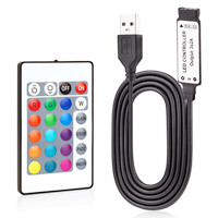
5V USB LED Controller |
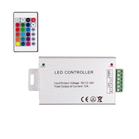
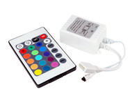
24v RGB LED Strip Controller
|
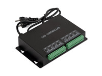
LED Slave Controller |
|
|
|
|
|
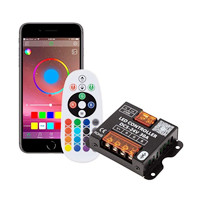
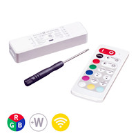
RGB Controller App |
Wi-Fi RGBW Controller |
RGB Controller Button |
|
|
|
|
(1) Product Packaging:
The product packaging should be free from damage and provide adequate protection.
Labels must display clear identification of relevant information, including P/O (Purchase Order), supplier, specification/model, product name, quality status label, production date, etc.
(2) Product Exterior:
For internal (bare board) power PCBs, components' surface-mounting and soldering should exhibit no solder bridging, solder voids, false soldering, or virtual soldering.
Components should not show significant misalignment, component floatation, missing components, incorrect placements, or damage.
External power supplies should have a visually intact exterior with no signs of damage or deformation.
Relevant parameter labels (as per marking requirements) and production cycle labels (for internal power supplies, markings should be present on the packaging) should be present for later identification and traceability.
The PCB version used for internal power supplies should match the sample, and the layout (silk-screened traces) should be consistent.
(3) Product Structure and Dimensions:
The product's external dimensions should conform to the drawings and sample requirements.
The specifications and spacing of mounting holes should meet the requirements.
Power cords and electronic wire heads supplied with the product should be tinned. The length of wires and tinning should meet assembly (post-soldering process) and installation requirements.
The specifications, dimensions, and compatibility of the plug-in components provided with the power supply should be verified and tested.
For external power supplies, the enclosure should be securely fastened, waterproofing gel should not overflow, and the PCBA should be securely fixed within the casing.
There should be no conductive foreign objects inside the housing of power supply components.
(1) Purpose: To test whether the power supply can withstand the impact of continuous switching operations.
(2) Equipment Used:
AC SOURCE (AC power source)
ELECTRONIC LOAD (electronic load)
OSCILLOSCOPE (oscilloscope)
4POWER ON/OFF TESTER (power on/off tester)
(3) Test Conditions:
Input Voltage: 115Vac/230Vac
Output Load: Full Load
ON/OFF Time: ON 5 seconds / OFF 5 seconds
ON/OFF Cycle: At least 5000 cycles
Ambient Temperature: Room Temperature
(4) Test Method:
① Connect the unit under test to the power on/off tester and power source (115Vac and 230Vac, full load, or as per customer specifications).
② Each cycle consists of turning the power OFF for 5 seconds and then turning it ON for 5 seconds. A total of 5000 cycles will be performed.
③ Record the input power and output voltage of the product after every 1000 cycles during the testing process.
④ After the test is completed, determine if there are any differences in the electrical performance of the unit under test before and after the test.
(5) Notes: Throughout the testing process and upon completion of the test, the unit under test should operate normally without any degradation in performance.
(1) Purpose: To test the temperature rise of components in the power supply under specified operating conditions, including voltage, frequency, load, and environmental conditions.
(2) Equipment Used:
AC SOURCE (AC power source)
ELECTRONIC LOAD (electronic load)
HYBRID RECORDER (DR130 hybrid recorder)
TEMP. CHAMBER (temperature-controlled chamber)
(3) Test Conditions:
According to SPEC. specifications: Input voltage (AC LINE), frequency (FREQUENCY), output load (LOAD), and ambient temperature.
(4) Test Method:
① Determine the component with the highest temperature rise based on the circuit conditions and apply a temperature rise line to the identified component.
② Set the test conditions (AC LINE and OUTPUT LOAD) according to the specifications, power on, and record the input power and output voltage.
③ Use the HYBRID RECORDER to record the temperature rise curve of the component. Print the results after the component temperature rise stabilizes and record the input power and output voltage.
(5) Notes:
① The temperature rise line joint point should be placed as close as possible to the component test point, and the trend of the temperature rise line should avoid affecting the heat dissipation of the power supply components.
② The tested samples should simulate their actual placement in the system.
③ For products without fans (NO FAN), try to avoid the influence of external airflow during testing.
(1) Purpose: To test the impact of high-temperature environments on the structure, components, and electrical performance of the power supply during operation. This is done to evaluate the rationality of power supply structural design and component selection.
(2) Equipment Used:
AC SOURCE (AC power source)
ELECTRONIC LOAD (electronic load)
AC POWER METER (power meter)
TEMP. CHAMBER (temperature-controlled chamber)
HI-POT TESTER (high-voltage tester)
(3) Test Conditions:
According to SPEC. requirements: Input conditions (RATED VOLTAGE), output load (FULL LOAD), and operating temperature (usually 40°C).
Test Duration: 4 hours.
(4) Test Method:
① Place the test sample in the temperature-controlled chamber, set the input and output test conditions according to the specifications, and then power on.
② Set the temperature and humidity of the temperature-controlled chamber according to the specifications, and then start the chamber.
③ Record the input power and output voltage of the test sample at regular intervals and check for any abnormalities.
④ After completing the test, allow the test sample to return to room temperature and keep it in a normal environment for at least 4 hours.
(5) Notes:
① The product's performance should not degrade or deteriorate during and after the test.
③ After the test, the dielectric strength and insulation resistance of the product should meet the specifications' requirements.
(1) Purpose: To conduct an accelerated test on all components of the power supply to reveal potential issues that may occur during actual operation.
(2) Equipment Used:
AC SOURCE (AC power source)
ELECTRONIC LOAD (electronic load)
AC POWER METER (power meter)
TEMP. CHAMBER (temperature-controlled chamber)
HI-POT TESTER (high-voltage tester)
(3) Test Conditions:
Operating temperature conditions: Typically low temperature at -40°C, ambient temperature at 25°C, 33°C, and high temperature at 66°C (humidity: 50-90%).
Testing for a minimum of 24 cycles.
(4) Test Method:
① Record the input power, output voltage, and HI-POT status of the test sample before the test.
② Place the confirmed test sample inside the constant temperature and humidity chamber without packaging, in a non-operational state.
③ Set the temperature sequence as follows: 66°C for 1 hour, 33°C and 90% humidity for 1 hour, -40°C for 1 hour, 25°C and 50% humidity for 30 minutes, constituting one cycle.
④ Start the constant temperature and humidity chamber, then record the temperature and time graph, monitoring the process recorded by the system.
⑤ After the test is completed, allow the temperature to return to room temperature, then remove the test sample from the constant temperature and humidity chamber. Place the sample in the air for 4 hours and then confirm if there are any abnormalities in appearance, structure, and electrical performance.
(5) Notes:
① The performance and appearance of the product should not degrade or deteriorate after the thermal cycling test.
② After the thermal cycling test, the dielectric strength and insulation resistance of the product should meet the specifications' requirements.
(1) Purpose: To test the impact of high and low-temperature shocks on the power supply, revealing weaknesses in various components.
(2) Equipment Used:
AC SOURCE (AC power source)
ELECTRONIC LOAD (electronic load)
AC POWER METER (power meter)
TEMP. CHAMBER (temperature-controlled chamber)
HI-POT TESTER (high-voltage tester)
(3) Test Conditions:
According to specification requirements: A total of 10 cycles, with storage at the highest (70°C) and lowest (-30°C) temperatures. The transition time between high and low temperatures should be <2 minutes.
According to the test conditions provided by the customer.
(4) Test Method:
① In the temperature-controlled chamber, the test sample is transitioned from room temperature (25°C) to the low temperature, typically -30°C, and held for 1 hour.
② The temperature-controlled chamber is then transitioned from the low temperature of -30°C to the high temperature, typically 70°C, with a transition time of 2 minutes, and held for 1 hour.
③ After 10 cycles between the high temperature of 70°C and the low temperature of -30°C, the power supply is removed when the temperature returns to room temperature (at least 4 hours of recovery time).
④ Confirm if there are any differences in the label, casing, withstand voltage, and electrical performance of the test sample compared to before testing.
(5) Notes:
① The performance and appearance of the product should not degrade or deteriorate after the thermal shock test.
② After the thermal shock test, the dielectric strength and insulation resistance of the product should meet the specifications' requirements.
③ The product is tested under non-operational conditions.
(1) Purpose: To test the impact of low-temperature storage environments on the electrical performance of the power supply, to assess the rationality of power supply electricals and component selection.
(2) Equipment Used:
AC SOURCE (AC power source)
ELECTRONIC LOAD (electronic load)
AC POWER METER (power meter)
TEMP. CHAMBER (temperature-controlled chamber)
(3) Test Conditions:
Low-temperature storage conditions: Typically, a decrease from the operational temperature of 0°C to -10°C. The storage time should be at least 4 hours.
(4) Test Method:
① Before the test, record the input power, output voltage, and HI-POT status of the test sample.
② Place the confirmed test sample in the temperature-controlled chamber, set the temperature according to the specifications, and then start the temperature-controlled chamber.
③ Store the test sample at the low temperature for at least 4 hours. Then, switch the power on and off 20 times under both 115Vac/60Hz and 230Vac/50Hz conditions with the maximum output load to confirm if the electrical performance of the test sample is normal.
(5) Notes:
① During or after product performance testing, the product's performance should not degrade or deteriorate.
② The set environmental temperature is 10 degrees lower than the operational low temperature.
8. LED Controller Abnormal Testing
Constant Voltage Power Supply Abnormal Testing: To assess compliance, perform the following tests at any voltage between 90% and 110% of the rated power supply voltage.
(1) Disconnect LED Module: If the control device is designed with multiple outputs, each corresponding output connected to the LED module should be opened circuit.
(2) Connect two times the number of LED modules as designed for the control device or equivalent loads in parallel to the control device's output terminals.
(3) Short-circuit the output terminals of the control device. If the control device is designed with multiple outputs, each corresponding output connected to the LED module should be short-circuited.
In the tests described above, each condition should be tested for 1 hour. After completion, the control device should not exhibit any safety-related faults, and there should be no generation of smoke or combustible gases.

Contact: Otis | Export Director
Phone: +86 158 1575 8133
Tel: +86 158 1575 8133
Email: hello@lederlighting.com
Add: No. 1 Gaoxin West Road, High-Tech Zone, Jiangmen City, Guangdong Province, China