Welcome: Jiangmen LEDER Lighting Co., Ltd.

The internal structure of an LED consists of a PN junction semiconductor, where the P-type semiconductor side is the positive pole and the N-type semiconductor side is the negative pole. Therefore, during usage, one end of the LED is connected to the positive pole, while the other end is connected to the negative pole, as shown in Figure 1. Typically, cannonball-shaped LEDs have a slightly longer positive pole, while high-power LEDs and SMD (surface mount type) LEDs are marked to indicate the negative pole. However, please note that product variations may exist under different circumstances. When installing an LED, it is important to pay attention to the polarity to avoid incorrect connections, as this can result in the LED not lighting up or even being damaged.
It is crucial to note that LEDs have a low reverse withstand voltage, usually just a few volts, and they cannot be directly connected to an alternating current (AC) circuit. If the design requires the use of an LED in an AC circuit, a reverse diode must be inserted.
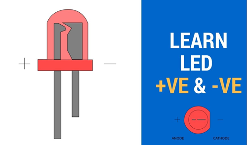
1 LED Positive and Negative
Do you know that the luminous flux and current of the LED are not necessarily proportional? If the current exceeds the rated value, problems such as overheating can occur. Consequently, the luminous output no longer increases proportionally, resulting in a saturation phenomenon. However, within the range of rated values, the general luminous flux maintains a proportional relationship with the current. Figure 2 illustrates an example of the current-light output characteristics of LEDs.
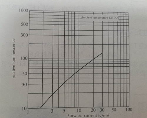
2 Figure 2 LED current-light output characteristic curve
Since the core of an LED is a PN junction, it has the electrical characteristics of a semiconductor diode. Figure 3 shows the volt-ampere (VI) characteristic curve of the LED.
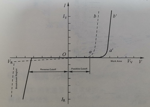
3 Figure3 Volt-ampere characteristic curve of LED
Point a shown in Figure 1-12 corresponds to the turn-on voltage (that is, the conduction threshold voltage). When the applied voltage V
When the applied voltage V
When the LED is reverse biased, it enters the reverse cut-off region, only a small reverse current flows through the LED, and the LED will not emit light. In the cut-off region, the reverse knee voltage VR of the curve is called the reverse breakdown voltage, and the current IR passing through the LED at this time is the reverse current.
When the applied voltage V<-VR, the LED enters the reverse breakdown region, and the reverse current increases sharply.
According to the volt-ampere characteristics of LEDs, the main electrical characteristic parameters of LEDs are summarized as follows:
① Forward (working) current IF. The forward working current refers to the forward current value of the LED when it is emitting light normally. The forward current IF of ordinary LEDs is usually only 10~20mA, while the IF of high-power white LEDs is usually 0.35~1.5A.
② Forward (working) voltage VF. The forward operating voltage refers to the voltage drop between the two electrodes of the LED when it passes the forward current IF. The forward operating voltage of traditional low-power color LEDs is mostly 1.4~2.8V (IF-20mA), while the forward operating voltage of white LEDs is usually 3~4V.
③Reverse (breakdown) voltage VR. Reverse breakdown voltage refers to the voltage drop between the two poles when the LED under test passes a specified reverse current (such as 10uA). Due to the different semiconductor materials used to make LED chips, the Vr value is also different. For example, VR=7V of InGaN LED, and VR of AlInGaP LED reaches 20V.
④Reverse current IR. Reverse current refers to the reverse current flowing through the LED when a certain reverse voltage is applied across the LED. The current is generally not greater than 10uA.
⑤ Allowable power consumption P. The allowable power consumption refers to the maximum power dissipation value to ensure the safe operation of the LED. When designing LED applications, the actual power consumption of the LED (P=IFVF) should not be greater than the allowable power consumption of the LED.
The volt-ampere characteristics of LED chips are affected by the material of the light-emitting chip. The biggest difference between LEDs and traditional light sources is that they have the characteristics of diodes. It can be seen from the volt-ampere characteristic curve that if the voltage changes slightly, the current will increase immediately, resulting in the constant and stable brightness of the LED. Therefore, when the applied voltage may exceed the forward voltage, it is recommended to connect the current limiting voltage, as shown in Figure 4; otherwise, when the applied voltage fluctuates, it will cause the forward voltage to overvoltage, form an overcurrent and pass through the LED, This can cause damage to the LED.
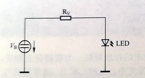
4 Figure 4.1 (a) The circuit diagram of constant voltage power supply series resistance for LED power supply
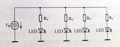
4 Figure 4.2 (b) LED parallel working configuration diagram
Even if the LEDs are connected in parallel. The volt-ampere characteristics of LEDs will vary with the product. In the case of parallel connection, the forward voltage will be the voltage value of the LED with the lowest voltage. At this point more current will flow through the lower voltage LED and only a small amount of current will flow through the higher voltage LED, resulting in a brightness difference between the LEDs, which can sometimes be a problem. If the current difference is too large, it may cause damage to the LED. When parallel connection is necessary, LED products with similar volt-ampere characteristics should be used.
Although LEDs have the characteristics of diodes, they do not have the reverse withstand voltage (usually a few volts) like rectifier diodes, so some products are equipped with anti-static protection diodes inside. These products will be short-circuited if a reverse voltage is applied, so if there is a possibility of reverse voltage in use, a reverse diode must be connected.
The response time of an LED is a crucial parameter that indicates its speed of response, particularly when subjected to pulse driving or electrical modulation. It refers to the duration taken by the LED to initiate light emission (rise) and to cease emitting light (decay) after applying a forward current. The rise time of the LED exhibits an approximately exponential decay with increasing current. For direct transition materials like GaAs1-X PX, the response time is as short as a few nanoseconds, while indirect transition materials like GaP have a response time of around 100 nanoseconds(ns).
From the point of view of use, the response time of LED is the delay time between LED lighting and extinguishing, as shown in tr and tf in Figure 5. The value of t0 in Figure 5 is very small and can be ignored. The response time of an LED depends primarily on the carrier lifetime, the junction capacitance of the device, and the circuit impedance.
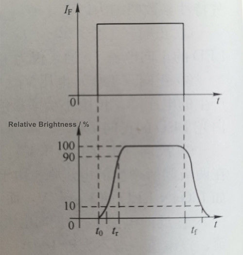
5 Figure 5LED Response Time Characteristic Chart
LED starts to emit light time tr (rise time). tr refers to the time elapsed from turning on the power to make the luminous intensity reach 10% of the normal value until the luminous intensity reaches 90% of the normal value.
LED off time tf[(falling time). tf[ is the time elapsed from normal luminescence to 10% of the original.
LEDs crafted from different materials exhibit varying response times. For instance, GaAs, GaAsP, and GaAlAs LEDs possess response times of less than 10^-9 seconds, while GaP LEDs have a response time of 10^-7 seconds. As a result, they can be employed in high-frequency systems ranging from 10 to 100 MHz.
A. Let's first understand the advantages of this high-voltage LED.
(a) High light efficiency. It is made of multi-core small chips connected in series, and the luminous efficiency is 5-10% higher than that of ordinary light sources with the same wattage through actual testing.
(b) Low power requirements. The high price and failure rate of power supply have been the primary problems that have hindered the development of the industry in recent years. High-voltage LEDs have inherent advantages. A small number of light sources can be used with a linear constant current driver to perfectly realize the efficient, safe and stable work of LEDs.
(c) The combination of linear power supply saves cost. When it comes to this, some people may say that the efficiency of linear constant current power supply is low. In fact, it depends on how you use it. In the past two years, there have been many linear constant current driver ICs on the market with good performance. If you plan to purchase linear constant current drivers, I can recommend them to you. I have tested a linear constant current IC called XX6137, and its efficiency can reach above 0.9. Due to the small size of the linear constant current IC and the absolute advantages of fewer peripheral components, the power drive part can be directly manufactured on the PCB, thus saving the space for installing the power supply compartment and related links such as installing the power supply (and power supply isolation), thus highlighting the advantages of cost control, warehousing, production capacity, delivery time and other costs.
(4) The superiority of the light source part. Since the traditional low VF value light source is used by connecting more than N units in series, the welding labor cost remains high, and products with poor welding emerge in endlessly, which affects the production capacity and brings a lot of secondary costs.
(5) Light decay. As the traditional light source is made by N series and N parallel, it is well known that the combination of light sources with inconsistent VF will cause the power loaded on each light source to be different, resulting in premature aging or dead light of some light sources, resulting in accelerated light decay of the whole light. The high-voltage lamp beads are multi-stringed, which can easily solve these problems.
B. Many bloggers will only tell about the advantages, and briefly mention the disadvantages. In my opinion, I think it is necessary to analyze what are the shortcomings of high-voltage LEDs?
(a) High cost. Due to the maturity of the technology of the upstream chip manufacturers and the lack of large-scale mass production of the chips, the chips are still at a high level. In addition, the production equipment of the original packaging companies cannot directly perform spectroscopic and color separation on the high-voltage light source, which is also a factor that causes the high cost. However, through the increasingly mature technology, mass production of large-scale tools and improvement of equipment, this pattern will soon be broken.
(b) Power dissipation and radiator issues. I also believe that when you search for "high-voltage LED advantages", many reports claim that the voltage of 1W high-voltage LEDs is 50V and the current is 20mA; while the voltage of ordinary low-voltage 1W LEDs is 3V and the current is 350mA, so "the power dissipation of high-voltage LEDs with the same output power is much lower than that of low-voltage LEDs during operation, which means that the cost of heat-dissipating aluminum casings can be greatly reduced." This statement is obviously not true. If you want to determine the size of the radiator, it should be calculated at the same luminous efficiency. It is generally believed that for the current luminous efficiency of 100lm/W, its true electro-optic efficiency (that is, the efficiency of converting electrical energy into light energy) is only about 30%, that is, only 30% of electrical energy is converted into light energy, and the remaining 70% of electrical energy is converted into thermal energy and needs to be dissipated through a radiator. Therefore, for 1W high-voltage LEDs and ordinary low-voltage LEDs with the same luminous efficiency, the part that turns into heat energy is 0.7W, which needs to be dissipated through the radiator.
(c) For the non-isolated application of the product, de-powering is bound to go through the de-powering process, so most of the products cannot be separated from the mains, which will cause the entire circuit to be electrified. However, plastic-clad aluminum and ceramic heat dissipation, heat-conducting plastics, etc. are good choices.
Introduced in the 1960s, the LEDs widely used today are known as "DC LEDs" as they are driven by direct current (DC). However, in January 2005, Seoul Semiconductor Corporation of South Korea became the world's first company to introduce the "AC LED," which operates directly on alternating current (AC) mains power. The Taiwan region of my country swiftly acquired proficiency in AC LED technology and achieved significant advancements in chip and packaging technology.
The current LED light source is a semiconductor device that operates at low voltage (Ve = 23.6V) and high current (IF = 2001500mA). To ensure proper light emission, it requires a suitable DC current. The technology for driving LED light sources with direct current (DC) has become increasingly mature. When DC LEDs are used in residential lighting, street and road lighting, architectural and landscape lighting, billboards, and outdoor screen displays, they are typically powered by the mains power supply at power frequency (110V/120V, 60Hz, or 220V/230V, 50Hz). In such cases, to enable normal operation of the DC LEDs, the AC power supply needs to be converted to AC/DC, and a DC/DC converter circuit must be added to provide a constant and appropriate DC working voltage for the DC LEDs. The specific scheme is illustrated in Figure 6.
|
Scheme 1 |
Scheme 2 |
|
AC 220V/50Hz or AC 110V/60Hz ↓ Voltage reduction by transformer ↓ Bridge rectification and filtering ↓ DC/DC step-down converter (constant current driver circuit) ↓ LED |
Bridge rectification and filtering ↓ Switching DC/DC step-down converter (constant current source) ↓ LED |
Figure 6 DC LED driving scheme powered by AC mains power supply
During the AC/DC and DC/DC conversion processes, the power loss can reach 20% or even exceed 30%, resulting in a significantly low system efficiency. Without installing a power factor correction (PFC) circuit after the bridge rectifier, the line power factor struggles to exceed 0.6, leading to low power utilization and the generation of excessive AC input current harmonics. The power conversion circuit requires numerous components such as transformers, inductors, aluminum electrolytic capacitors, and power transistors. These components are large and bulky, making it challenging to design LED bulbs and accommodate them within limited space while addressing heat dissipation concerns. To ensure the performance of the dynamic power supply, the circuit cannot be overly simplified. The more components used in the circuit, the larger the footprint, space requirements, and cost, consequently reducing reliability. Although current DC LEDs have a lifespan of over 30,000 hours, in practical applications, LEDs often fail well before reaching this threshold. The failures are usually attributed to damages in components like electrolytic capacitors or power transistors within the drive circuit.
In contrast, AC LEDs only require a series connection with a current-limiting resistor to be directly powered by the AC mains supply. They eliminate the need for AC/DC conversion and do not require a DC/DC step-down constant current source drive circuit. AC LEDs offer convenient application and simple design. Moreover, their extremely small size completely revolutionizes the traditional LED application scheme.
AC LEDs usually only need to be connected in series with a current-limiting resistor to be directly driven by an AC power source, as shown in Figure 7. When the AC LED is AN2200/AW2200, the AC power supply voltage should be 100V/110V. In this case, see Table 1-6 for the VF steps provided by the manufacturer and the recommended current-limiting resistor values.
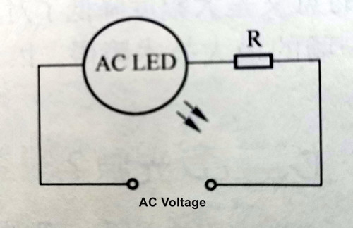
7 Figure 7 AC LED Typical Driving Circuit
Table 1-6 VF classification and current limiting resistor value of AN2200/AW2200
|
VF Binning |
100V |
110V |
|
A |
720Ω |
1120Ω |
|
B |
540Ω |
1020Ω |
|
C |
440Ω |
940Ω |
|
D |
400Ω |
860Ω |
If the AC LED is AN3200/AW3200 or AN3220/AW3220, see Table 1-7 for the working voltage V level and current limiting resistor value.
Table 1-7 VF classification and current limiting resistor value of AN3200/AW3200 and AN3220/AW3220
|
VF Binning |
AN3200/AW3200 |
AN3220/AW3220 |
||||
|
Drive Current:40mA |
Drive Current:20mA |
|||||
|
Resistance R/Ω |
Resistance R/Ω |
|||||
|
100V |
110V |
120V |
220V |
230V |
240V |
|
|
A |
300 |
500 |
750 |
2.2 |
2.6 |
3 |
|
B |
250 |
450 |
700 |
1.9 |
2.35 |
2.75 |
|
C |
200 |
400 |
650 |
1.63 |
2.1 |
2.55 |
|
D |
- |
350 |
600 |
1.36 |
1.85 |
2.3 |
Two 100V/110V AC LEDs (such as AN2200/AW2200) can be connected in series and connected to a current limiting resistor, and driven by 220V/230V AC power, as shown in Figure 8. See Table 1-8 for AN2200/AW2200 VF steps and recommended current limiting resistor values.
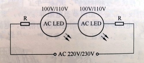
8 Figure 8 AC220V230V power supply drives two 100V110V AC LEDs connected in series
Table 1-8 VF classification and current limiting resistor value of AN2200/AW2200
|
VF Binning |
200V |
110V |
|
A |
2.2kΩ |
2.7kΩ |
|
B |
2kΩ |
2.4kΩ |
|
C |
1.8kΩ |
2.2kΩ |
|
D |
1.6kΩ |
2kΩ |
Contact: Otis | Export Director
Phone: +86 158 1575 8133
Tel: +86 158 1575 8133
Email: hello@lederlighting.com
Add: No. 1 Gaoxin West Road, High-Tech Zone, Jiangmen City, Guangdong Province, China