Welcome: JiangMen Leder Lighting Co,, Ltd

There are several different structures for LED fluorescent lamp driver power supplies. Many people have a limited understanding of switch-mode power supplies and often mistakenly believe that an isolated circuit refers to a buck (step-down) circuit; and that if a buck circuit fails, the LED will be damaged. In reality, commonly used non-isolated topologies are not limited to buck circuits; there are at least three types: buck, buck-boost, and boost circuits, each with its own characteristics.
The main characteristic of a buck circuit is that it is suitable for high-current output applications. However, when used with LEDs, a failure in the power supply can lead to LED damage. The buck-boost circuit's main feature is that it can both increase and decrease the output voltage. If the switching transistor malfunctions, the LED remains undamaged. A common variant of this circuit is the isolated flyback topology. The boost circuit is a practical design with the highest output power and minimal heat generation. In case of a power supply failure, it won't harm the LED. This makes it the most suitable option for LED fluorescent lamp drivers. However, it requires a minimum output voltage, so LEDs must reach a certain power level; otherwise, a buck-boost circuit must be used.
The constant current mode in LED fluorescent lamp driver power supplies has certain characteristics. Currently, there are two different control modes for maintaining a constant current in LED driver circuits, and these two modes result in significantly different operational characteristics in terms of principles, device applications, and performance.
The first mode, represented by constant current-type LED-specific ICs such as the 9910 series and AMC7150, is commonly referred to as "constant current Type C." However, using this type of constant current IC for LED driving may not yield optimal results. The control principle of this mode is relatively simple: it sets a current threshold in the primary circuit of the power supply. When the primary MOSFET is on, the inductor current increases linearly until it reaches the threshold, at which point the MOSFET turns off, and the inductor current decreases linearly. In the next cycle, it is triggered again by the control circuit. This type of circuit can actually be considered a current limiting circuit. The slope of the inductor current varies with different inductor values, input voltages, and loads, leading to variations in the average LED current. As a result, maintaining consistent current levels can be challenging, especially in mass production, where inductor values may have slight variations (typically controlled within ±10% during factory production). Another characteristic of this mode is that the output current is typically triangular or fluctuating in nature, and it usually does not require additional electrolytic smoothing capacitors. However, this can be problematic because excessive current peaks can affect LEDs. Generally, power supplies of this type do not have parallel electrolytic capacitors for current smoothing.
The second constant current mode should be referred to as "switching power supply" mode. In this mode, common switch-mode power supply ICs are used as the core conversion devices. There are various control chips available for this mode, such as PowerInt's TNY series, TOP series, ST's VIPer12/IPer22, VIPer53, Fairchildsemi's FSD200, and even simple RCC circuits using only transistors or MOSFETs. The advantages of this mode include lower cost and good reliability because these switch-mode power supply chips are cost-effective and have been extensively used as classic products. These ICs often integrate the MOSFET, making them convenient compared to using an external MOSFET like HV9910. However, the control in this mode is somewhat more complex and requires an external constant current control component, which can be a transistor or operational amplifier. Magnetic components can be iron core inductors or high-frequency transformers with air gaps. This control mode is somewhat similar to the constant voltage control mode in typical switch-mode power supplies. A TL431 is used as a voltage reference because it has a precise 2.5V internal reference source. A resistor voltage divider is used to detect the output voltage. When the output voltage increases or decreases slightly, a comparison voltage is generated, and this voltage is used to control the PWM signal through comparison and amplification in the feedback loop. This allows for very precise voltage control. Similarly, for constant current regulation, a constant current reference and operational amplifier are needed, using resistor-based current sensing as the control signal. This signal is then amplified and used to control PWM modulation. Unfortunately, finding highly accurate current reference sources can be challenging. Common options include transistors (which can exhibit significant temperature drift) and diodes with approximately 1V forward voltage drop (with limited accuracy). The best approach is to use an operational amplifier in combination with TL431 as a reference, although this results in a more complex circuit. Constant current power supplies made this way can offer much better control over current accuracy.
The key difference in this mode is that the output must include an electrolytic capacitor for smoothing. Therefore, the output voltage is a smoothed DC rather than pulsating. If you see an electrolytic capacitor in the output, it likely belongs to this control mode.
Whether using a current-limiting constant current control power supply or a constant current power supply controlled by an operational amplifier, the issue of supplying power to the driver chip must be addressed. In other words, a relatively stable DC voltage is required to power the chip when it operates. The current for the chip typically ranges from 1mA to a few milliamperes.
Chips like FSD200, NCP1012, VIPer22, and HV9910 are self-powered from high voltage sources, making them convenient to use. However, the high-voltage supply leads to increased heat generation in the driver chip, as the chip has to withstand around 300V DC, even if the current is only 1mA, resulting in a power loss of 0.3W. In typical LED power supplies with around 10W of output power, losing a fraction of a watt can significantly reduce the conversion efficiency of the power supply.
Another approach is seen in chips like QX991PT4107, which use a resistor for pull-down to supply power. In this case, the power loss occurs in the resistor and is typically just a fraction of a watt. Additionally, some designs use transformer-based solutions, where an auxiliary winding is added to the main power line, similar to an auxiliary winding in a flyback power supply. This approach helps avoid power losses of a fraction of a watt. One of the reasons for using transformers in non-isolated power supplies is to eliminate this fractional watt power loss, thus increasing efficiency by a few percentage points.
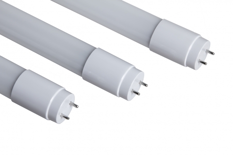
LED fluorescent lamps, including T8 tube lights and T5 tube lights, have become a staple in modern lighting solutions. Their energy efficiency, longevity, and eco-friendliness make them a preferred choice for businesses and homeowners worldwide. We take pride in being a leading player in this mature and ever-evolving market.
Today, I would like to shift our focus from product introduction to the core elements that power these remarkable lighting solutions: drivers and chips. It is the synergy between innovative driver technology and cutting-edge chipsets that enables us to offer high-performance LED fluorescent lamps that are not only energy-efficient but also durable.
One of the key strengths of our company is our ability to provide exceptional OEM services. Our commitment to quality and competitive pricing has made us the preferred partner for numerous clients. Many of them return year after year, a testament to our consistency in delivering value.
Furthermore, we are proud to offer waterproof LED fluorescent lamps that are renowned for their exceptional quality. Our commitment to maintaining the highest standards has resonated with customers, and these waterproof solutions have gained immense popularity in the market.
We believe that there is great potential for growth and collaboration in this dynamic industry. As we look to the future, we envision pushing the boundaries of LED fluorescent lamp technology even further. This includes exploring advanced driver solutions, enhancing chip efficiency, and developing innovative product variants to meet evolving customer needs.
To this end, we invite you to join us on this exciting journey. Let's continue our partnership, leveraging our strengths and expertise, to create even more outstanding LED fluorescent lamp solutions. Together, we can shape the future of lighting technology.
Contact: Mr. Otis
Phone: +8615815758133
Tel: +8615815758133
Email: Hello@lederlighting.com
Add: No. 1 Gaoxin West Road,High-tech Zone, Jiangmen, Guangdong, China