Welcome: JiangMen Leder Lighting Co,, Ltd

BP2808 is a constant current control chip specially designed to drive LED light sources. It operates in a continuous current mode in a buck system, and it achieves a constant average current for LED light sources by controlling the peak current and ripple current of the LED. The chip requires very few external components to achieve functions such as constant current control, analog dimming, and PWM dimming. The system voltage range is DC12600V, with a maximum duty cycle of up to 100%. It is suitable for wide voltage input from AC 85265V and is mainly used in non-isolated LED lamp power supply and drive systems. BP2808 employs patented source driving and constant current compensation technology, ensuring a constant current for driving LED light sources, with a variation of less than 3% in the AC 85265V range. Combined with the application circuit of the driving system using BP2808's patented technology, it provides a practical solution for 18W LED fluorescent lamps, achieving system efficiency of over 90% within the AC 85265V range. BP2808 can drive LED light source arrays ranging from 3 to 36W within the AC 85~265V range, making it suitable for a wide range of applications, including E14, E27, PAR30, PAR38, GU10, and other lamp cups and LED fluorescent lamps.
BP2808 comes with multiple LED protection functions, including LED open circuit protection, LED short circuit protection, and over-temperature protection. In the event of a system fault, the power system automatically enters a protection state until the fault is resolved, after which the system automatically returns to normal operation mode. The DIM pin can be used for LED analog dimming, PWM dimming, and dynamic temperature protection for the lighting system. BP2808 is packaged in SOP-8, as shown in Figure 6-15, and the functions of each pin are listed in Table 6-4.
Figure 6-15: Pin Diagram of BP2808
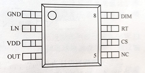
Figure 6-15 BP2808 pin diagram
Table 6-4 Pin functions of BP2808
|
Pin number |
Pin name |
Describe |
|
1 |
GND |
Signal and power ground |
|
2 |
LN |
Line voltage compensation for peak and threshold, sampling the voltage between pin LN and pin VDD |
|
3 |
VDD |
The power input terminal must be connected to a bypass capacitor nearby. |
|
4 |
OUT |
The drain terminal of the internal power switch, the source terminal of the external power switch |
|
5 |
NC |
Hanging in the air |
|
6 |
CS |
Current sampling terminal, the sampling resistor is connected between pin CS and pin GND |
|
7 |
RT |
Set the chip shutdown time |
|
8 |
DIM |
Switch enable, analog dimming and PWM dimming end |
The characteristics of BP2808 are as follows:
The system operating voltage range is from DC12V to 600V, supporting input voltages from AC85V to 265V.
The duty cycle ranges from 0% to 100%.
Output current accuracy of 35%.
System efficiency of up to 93%.
LED short-circuit protection and LED open-circuit protection.
Internal chip over-temperature protection.
Multiplexed pin DIM for LED analog dimming, PWM dimming, and dynamic system temperature compensation.
There are various power supply and drive solutions for the light sources in LED fluorescent lamps. Currently, non-isolated solutions are dominant due to their high efficiency, small size, and low cost. Additionally, the majority of LED fluorescent lamps use PWM LED driver controllers as their power sources. In fact, traditional fluorescent lamps typically employ non-isolated solutions.
Taking AC176~264V as an example of the full voltage input range, when designing a low-power LED fluorescent lamp with multiple LED light sources in series or parallel, the overall system design diagram with BP2808 as the main chip is shown in Figure 6-16. The entire circuit includes surge/surge protection, EMC filtering, full bridge rectification, passive power factor correction (PFC), startup voltage (including feedforward compensation, post-start feed current suppThe design of the LED light source array consists of 288 small-power white LEDs (SMT or cap) connected in series in groups of 24, with 12 groups connected in parallel. This configuration drives a total of 288 small-power WLEDs with a combined power of 18W. The schematic diagram of the 18W LED lamp's switch constant current source design circuit is shown in Figure 6-17, with the functions of each section indicated by Chinese characters in the diagram. The EMC circuit, comprised of surge protection and EMI filtering, is shown in the diagram, and feedforward compensation is achieved using the chip's internal rectifier diode.
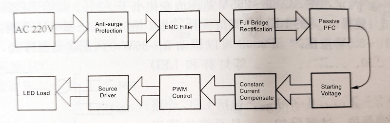
Figure 6-16 LED fluorescent lamp system design block diagram
Figure 6-17: Schematic Diagram of the 18W LED Fluorescent Lamp System Design Circuitly, soft start), constant current compensation, PWM control, source driving, LED light source array, as well as sampling resistors, toee time setting, energy storage inductors, and freewheeling diodes, among other components.
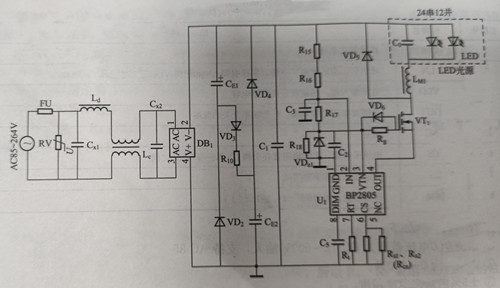
Figure 6-17 18W LED fluorescent lamp system design circuit diagram
The design of the LED light source array consists of 288 small-power white LEDs (SMT or cap) connected in series in groups of 24, with 12 groups connected in parallel. This configuration drives a total of 288 small-power WLEDs with a combined power of 18W. The schematic diagram of the 18W LED lamp's switch constant current source design circuit is shown in Figure 6-17, with the functions of each section indicated by Chinese characters in the diagram. The EMC circuit, comprised of surge protection and EMI filtering, is shown in the diagram, and feedforward compensation is achieved using the chip's internal rectifier diode.
Looking at AC220V, the circuit consists of the following components:
① A 1A fuse (FU) and surge, lightning, and surge-resistance resistors (RV) at the mains input.
② An EMI filter composed of Ld, Lc, Cxl, and Cx2.
③ BD serves as a full bridge rectifier, containing four high-voltage silicon diodes internally.
④ A passive power factor correction (PFC) circuit comprised of CE1, CE2, R10, VD2~VD4.
⑤ BP2808 chip, powered by R15, and R16 for startup voltage reduction through R17 and C3. It also includes feedforward compensation using VZ, C2, and R18, and provides power to BP2808's control circuit after voltage stabilization. After system startup, the static current of the control circuit is minimal, and BP2808 benefits from the feedforward diode from OUT to VCC, significantly reducing the current passing through R15~R17 and, thus, reducing overall system power consumption and increasing system efficiency.
The patented source driving circuit consists of MOSFET VT, VD6, Rg, R1, Rcs, and BP2808's internal circuitry. Its significant feature is the effective reduction of power consumption and improved constant current accuracy. The source driving method in the driving circuit reduces the current consumption in the system, especially in components similar to R15~R17 in the traditional high-voltage differential power supply path, thereby reducing power consumption and improving efficiency. VD6 and Rg help VT conduct for soft switching and maintain strong off-state drive, improving EMI while preserving efficiency as much as possible. The output filter capacitor Co, connected in parallel with the LED light source, reduces current ripple on the LED light source.
The CS terminal of BP2808 samples the peak current on the current-sensing resistor Rs3Rs3 and controls the duty cycle of the OUT signal within a single cycle through internal logic for constant current control. The constant current output combines with VD5 and Lm in the freewheeling circuit to supply constant current to the LED light source. When the LED light source array configuration changes, the resistance values of Rs3Rs3 must also change to ensure that the entire circuit's output current meets the requirements of the LED light source array configuration.
The arrangement of the PCB (Printed Circuit Board) is crucial for product quality, and PCB routing should follow the requirements of power electronics safety standards. This circuit is applicable to T10 and T8 fluorescent lamp tubes. Since the sizes of the two tubes are different, the widths of the two printed circuit boards will also differ. To minimize the height of all components for installation in T10 and T8 lamp tubes.
If designed for full voltage input AC85~264V with consideration for PFC, the LED light source array can be configured with 12 series-connected 0.06W white LEDs in 24 parallel groups. When using BP2808 as the power supply driver for LED fluorescent lamps, it is recommended to keep the output DC voltage below 100V and the current below 600mA.
Currently, there are several LED fluorescent lamp driver chips available, each with different performance parameters. Table 6-5 provides reference information for selecting the appropriate chip for your design. From the table, you can see that BP2808 offers distinct advantages for LED lighting fixtures, such as its fixed tOFF operating mode, 100% duty cycle, low chip operating current (only 0.2mA), 92% efficiency, constant current compensation, and the use of a unique source driving mode, making it highly suitable for LED lighting applications.
|
product |
Operating |
Maximum |
Output |
Drive mode |
Chip |
Drive |
Typical |
Constant |
Short |
EMC |
MOS |
Power |
|
XX9910 |
fixed fsw |
0~55 |
big |
Gate Drive |
1~2 |
7.5 |
90 |
not |
not |
very difficult |
high |
NO |
|
XX4107 |
fixed fsw |
0~55 |
big |
Gate Drive |
1~2 |
12 |
85 |
not |
not |
very difficult |
high |
YES |
|
XX802 |
fixed fsw |
0~55 |
big |
Gate Drive |
1~2 |
7.5 |
90 |
not |
not |
very difficult |
high |
NO |
|
XX870 |
fixed fsw |
0~55 |
big |
Gate Drive |
1~2 |
9.6 |
90 |
not |
not |
very difficult |
high |
NO |
|
XX306 |
fixed fsw |
0~55 |
big |
Gate Drive |
1~2 |
7.5 |
85 |
not |
not |
more difficult |
high |
NO |
|
XX9910B |
Fixed t OFF |
0~100 |
middle |
Gate Drive |
1~2 |
7.5 |
90 |
not |
not |
more difficult |
high |
NO |
|
XX3445 |
Fixed t OFF |
0~100 |
middle |
Gate Drive |
1~2 |
12 |
85 |
not |
not |
more difficult |
higher |
YES |
|
XX3910 |
Fixed t OFF |
0~100 |
middle |
Gate Drive |
1~2 |
7.1 |
85 |
not |
not |
more difficult |
high |
YES |
|
BP2808 |
Fixed t OFF |
0~100 |
middle |
Gate Drive |
1~2 |
12 |
92 |
not |
not |
more difficult |
low |
NO |
|
>50% harmonic oscillation |
||||||||||||
The key technologies of BP2808 in LED fluorescent lamps include constant current compensation and source driving, both of which are patented application circuits that make BP2808 more convenient and distinctive. As shown in Figure 6-18, BP2808's internal circuitry between GND and LN constitutes the patented application circuit for constant current compensation, utilizing components such as R3, C3, R4, D1, and C2. On the other hand, the internal circuitry between BP2808's VCC, CS, and OUT forms the patented application circuit for source driving, using components like Q1, D6, Rg, R1, and Rcs.
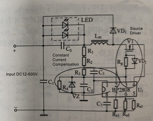
Figure 6-18 Two patented application circuits of constant current compensation and source drive
Figure 6-19 illustrates the principle of the source driving control circuit, showing that the low-voltage switch MOSFET (700mA) inside BP2808 is connected in a drain-to-source configuration to the external power switch MOSFET VT, with its source connected to one end of the current-sensing resistor Rcs and the input of the first comparator. The gate of the MOSFET is connected to the output of the RS flip-flop. The output current from the drain of the external power switch MOSFET VT directly drives the LED light source through the energy storage inductor. VD0 inside the chip is a feedforward diode that provides working power to BP2808 by rectifying the feedforward current from OUT to VCC after BP2808 starts working.
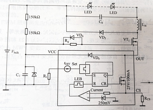
Figure 6-19 Source drive control circuit schematic diagram
Using source driving can effectively reduce current consumption in the driving circuit, lower power consumption, and improve efficiency. In traditional high-voltage differential power supply paths, significant power is dissipated in high-resistance, high-power resistors to reduce the rectified high-voltage DC to the low-voltage working voltage required by PWM chips, leading to device heating and high self-consumption.
BP2808 can also be applied to design drive power supplies for LED lighting fixtures such as isolated and non-isolated bulbs, PAR lamps, tube lights, embedded lights, courtyard lights, explosion-proof lights, wall washers, desk lamps, work lights, and TRIAC dimming lights, among others. The design principles for non-isolated fixtures can follow the typical application design approach mentioned earlier for LED fluorescent lamps, with changes in the arrangement of the LED light source arrays to create various styles and forms of LED fixtures. Depending on the different requirements of various LED fixtures for the driving power supply, the output characteristics of the power supply can be modified to meet specific needs. For example, TRIAC dimming control can be achieved by adding a signal extraction circuit for conduction angle in the application circuit and using this signal to control the driving current of the LED light source, achieving dimming effects.
BP2808's fixed tOFF operating mode, 100% duty cycle, reduced chip operating current to 0.2mA, and efficiency of up to 92% enhance its suitability for applications in LED lighting fixture drive power supplies. In addition to inheriting and absorbing the advantages of similar products domestically and internationally, BP2808 also employs an innovative topology structure and significant improvements in chip design, resulting in more refined performance. Notably, the two patented application circuits for constant current compensation and source driving make BP2808 more convenient and energy-efficient in its applications.
Contact: Mr. Otis
Phone: +8615815758133
Tel: +8615815758133
Email: Hello@lederlighting.com
Add: No. 1 Gaoxin West Road,High-tech Zone, Jiangmen, Guangdong, China