Welcome: Jiangmen LEDER Lighting Co., Ltd.

As shown in Figure 5-1, LEDs are connected in a series, meaning that the positive terminals of multiple LEDs are connected to the negative terminals. The advantage of this configuration is that each LED operates with the same current, typically controlled by a current-limiting resistor, R. Series connection requires the LED driver to output a higher voltage. When there is a significant variation in LED consistency, the voltage across LEDs located at different ends may differ. With each LED having the same current, there is generally better brightness uniformity among the LEDs. In the event of a short circuit in one LED, if a constant voltage power supply is used, the voltage distributed to each LED increases due to the fixed output voltage, resulting in an increased driver output current. If the LED current exceeds the rated value by too much, it can lead to excess light output from the remaining LEDs, shortening their lifespan or even causing them to burn out. If a constant current power supply is used, when one LED experiences a short circuit, since the driving current remains unchanged, it will not affect the normal operation of the remaining LEDs. When one LED experiences an open circuit, all LEDs connected in series will turn off. In such cases, a voltage-regulating diode can be connected in parallel at the terminals of each LED, as shown in Figure 5-2. The selected voltage-regulating diode should have a forward voltage higher than the forward voltage drop across the LEDs connected in parallel with it; otherwise, the LED will not light up.
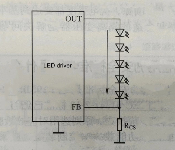
Figure 5-1 All LEDs connected in series
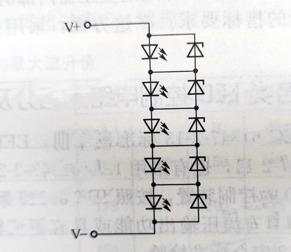
Figure 5-2 LED zener diode connected in parallel at both ends
In offline LED lighting power supplies, the DC output voltage of the flyback converter is limited by the voltage rating of the components. For example, the silicon Schottky diodes currently used as rectifiers typically have a reverse breakdown voltage not exceeding 100V. These rectifier diodes can only be used in switching power supplies with an output voltage of 1224V. Since the forward voltage drop of high-power white LEDs is usually around 3.54.2V, the series connection scheme is no longer suitable when the number of LEDs in the LED array exceeds 10.
As shown in Figure 5-3, LEDs are connected in parallel, which requires the LED driver to output a higher current and a lower load voltage. In this configuration, each LED has the same voltage, and the total current is the sum of the current flowing through each LED. When there is a significant variation in LED consistency, the brightness of each LED may differ due to the different currents flowing through them.
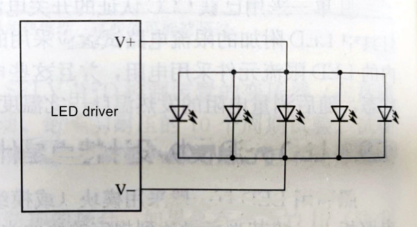
Figure 5-3 LEDs are all connected in parallel
In the case of a defective LED that opens when using a constant voltage driver, the power supply's output current will decrease, but it won't affect the normal operation of the remaining LEDs. However, if a constant current driver is used, the total output current remains constant, which means that the current distributed to each LED increases in the event of a single LED failure. This can potentially damage all the LEDs. Therefore, this all-parallel connection method is not suitable for situations with a small number of LEDs because if one LED opens, each remaining LED has to carry an additional higher current. However, when a larger number of LEDs are connected in parallel, the impact on the remaining LEDs is minimal when one LED opens. Therefore, when choosing an all-parallel connection, a constant current driver should not be selected. If one LED shorts due to a defect, all the LEDs will not light up.
In mixed connection, LED arrays can be connected in two ways: series-parallel (first in series, then in parallel) and parallel-series (first in parallel, then in series), as shown in Figure 5-4.
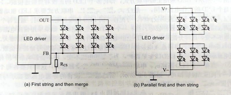
Figure 5-4 LED mixed connection
For example, if an LED streetlight has a power rating of 50W, it would require 50 individual 1W white LEDs. When using a series connection scheme, if each LED has a forward voltage drop of 3.5V, the total voltage drop across the array of 50 LEDs would be 175V. Achieving such a high voltage is challenging for offline switch-mode power supplies.
However, if you arrange the 50 LEDs into 10 rows, with each row containing only 5 LEDs, the total voltage drop across the LEDs in each row would be only 17.5V. This voltage level is easier to achieve with a driver power supply. The mixed connection scheme can effectively address current balancing issues for LED arrays above 20W.
This mixed connection approach allows for greater flexibility in designing LED arrays with varying voltage and power requirements.
LED cross-array connection is a special type of mixed connection, as shown in Figure 5-5. The advantage of the cross-array connection scheme is that it helps improve the reliability of LED modules. Even if one LED fails, as long as the number of LEDs in the array is not too small, it will not result in the entire LED array going completely dark.
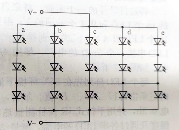
Figure 5-5 Circuit diagram of LED using cross array form
Four identical LED units from different batches were tested at 25°C with a current source of 1A to measure the forward voltage drop VF of each LED separately (see Figure 5-6), and the test results are shown in Table 5-5. In order to minimize the influence of chip thermal effects, readings were recorded within 5 seconds after powering on. Figure 5-6(b) shows another experimental circuit in which four identical LEDs are arranged in parallel in four rows and driven with a 4A current source, and the current IF passing through each LED is measured at the same voltage of VF 2.56V. Table 5-6 presents the measured results.
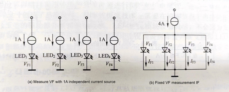
Figure 5-6 Fixed IF measurement VF and fixed VF measurement IF circuit diagram
Table 5-5 VF values at the same IF
|
LED serial number |
IF/A |
VF/V |
|
1 |
1 |
3.83 |
|
2 |
1 |
3.41 |
|
3 |
1 |
3.59 |
|
4 |
1 |
3.52 |
Table 5-6 IF values when using the same VF
|
LED serial number |
VF/A |
IF/A |
|
1 |
3.56 |
0.45 |
|
2 |
3.56 |
1.53 |
|
3 |
3.56 |
0.91 |
|
4 |
3.56 |
1.1 |
From Table 5-5, it can be seen that the voltage difference (VF) between LED 1 and LED 2 is 3.83V - 3.41V = 0.42V. At V = 3.56V (see Table 5-6), the current through LED 2 is 1.53A / 0.45A = 3.4 times that of LED 1, which will result in a significant difference in luminous intensity.
Now, let's proceed with another experiment. Sixteen LEDs from the same VF group and sixteen LEDs randomly selected from four different VF groups are arranged in a 4x4 array configuration, with each LED in series with a 5mΩ resistor, all powered by a 4A power source, as shown in Figure 5-7.
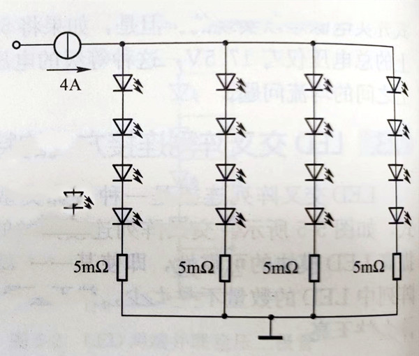
Figure 5-7 Circuit for measuring current matching between rows
Each LED array is initially powered on in a 25°C environment, and the current through each row of LEDs is recorded within 5 seconds. Afterward, each array is powered on for an additional 0.5 hours, and the PCB temperature at thermal steady-state and the current through each series of LEDs are measured using a handheld IR probe. The measurement results are shown in Tables 5-7 and 5-8, respectively.
Table 5-7 Row current of the same VF group
|
Rows |
IF/A at 25°C |
PCB temperature at thermal stability/°C |
IF/A at thermal steady state |
|
1 |
1.08 |
93.4 |
0.92 |
|
2 |
1.06 |
128 |
1.34 |
|
3 |
1.02 |
112 |
0.96 |
|
4 |
0.84 |
94 |
0.8 |
Table 5-8 Row currents of different VF groups
|
Rows |
IF/A at 25°C |
PCB temperature at thermal stability/°C |
IF/A at thermal steady state |
|
1 |
1.48 |
114 |
1.38 |
|
2 |
0.68 |
95 |
0.76 |
|
3 |
1.24 |
113 |
1.26 |
|
4 |
0.66 |
80.8 |
0.58 |
The measurement results in Table 5-7 indicate that at 25°C, LEDs with the same VF in both series and parallel-connected LED arrays can achieve current balance. In LED arrays where VF is from different groups and there is VF mismatch, the worst-case scenario occurs in the 1st and 4th rows (as shown in Table 5-8), with a difference in LED current of 1.48A - 0.66A = 0.82A. However, even when LEDs are from the same VF group and VF is reasonably matched, there is still a difference of approximately 0.24A (as seen in Table 5-7), which is about 25% of the 1A target DC current. Furthermore, once LED chips start to self-heat, the current in the matched array gradually loses balance, similar to the unmatched array.
Currently, most LED manufacturers provide LEDs in reel packaging or bag packaging with LEDs from a single group. However, it is not possible to ensure that every LED purchased belongs to the same group. Regarding the VF grouping of LEDs, if the VF difference between LED groups is within 1mV, it can significantly improve current sharing ability at room temperature, but this will inevitably increase costs. Despite the substantial effort required for LED sorting and grouping, this process is essential.
To improve the current-sharing ability of individual LEDs in an LED array, for certain applications, you can add a current-limiting resistor to each LED in series. Additionally, you can add current regulators to each row of LEDs or incorporate a linear regulator in an ion trap/power supply flow. The best solution is to drive them using a switching regulator.
Currently, there are a significant number of high-power LEDs used in lighting, typically ranging from several tens to even hundreds. Choosing the appropriate driving and matching methods becomes crucial. However, each of the aforementioned driving methods has its own advantages and disadvantages. For high-power LED power supplies, the prevalent design approach for future LED lighting is to use a constant voltage followed by a constant current. This approach is referred to as distributed constant current, and its main architecture is illustrated in Figure 5-8.
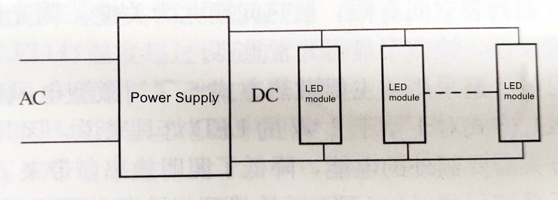
Figure 5-8 Distributed Constant Current Architecture Diagram
In this approach, a switching voltage regulator is first used to provide a stable direct current voltage. Then, LED modules with constant current devices are connected to the direct current output. This distributes the constant current technology within the light source, forming a relatively independent module with the LED. This design offers high flexibility, simplifies power supply specifications, and allows for the selection of different numbers of LED modules based on varying luminous flux requirements. The division into LED modules makes high-power LED lighting particularly suitable for applications such as streetlights, tunnel lights, public area lighting, and advertising light boxes. Distributed constant current design LED products exhibit exceptional product stability. In distributed constant current technology, the voltage regulator section can continue to use traditional switching power supplies to provide constant voltage power. The accumulated experience in switching power supply technology has created quality conditions for LED driver power supply design. Distributed constant current technology also requires the connection of low voltage drop linear constant current drivers at the constant current nodes, with low voltage drop drivers contributing to drive efficiency. The flexible configuration of LED constant current modules ensures that changes in branch currents do not affect the operation of other branches. Distributed constant current allows for the flexible arrangement of parallel branches and LED modules according to application requirements, thus maintaining stable currents in both individual branches and the overall circuit. The stability of the driver circuit directly impacts the overall product stability, and distributed constant current offers unique advantages in terms of stability.
If you encounter any difficulties or have further questions, please do not hesitate to contact our customer support team. We are committed to assisting you throughout your project's development and implementation.
I hope you choosing us as your LED strip provider. We look forward to a successful collaboration and the illumination of your new project.
Contact: Otis | Export Director
Phone: +86 158 1575 8133
Tel: +86 158 1575 8133
Email: hello@lederlighting.com
Add: No. 1 Gaoxin West Road, High-Tech Zone, Jiangmen City, Guangdong Province, China