Welcome: Jiangmen LEDER Lighting Co., Ltd.

When it comes to the design and usage of LED lamps, the topic of heat dissipation is always essential.
LED light sources require power and a heat management system because, unlike other light sources, most of the electrical energy supplied to LEDs is converted into heat. Without proper heat management, this heat can affect the LED's lifespan and color output. Addressing the heat dissipation issue in LED lighting fixtures is an indispensable aspect of fixture design.
(1) Choosing LED Light Sources with Excellent Heat Dissipation Performance
In the design of luminaire heat dissipation systems, the first step is to select LEDs or LED modules with low thermal resistance and excellent heat dissipation performance.
To address the heat dissipation issue of LEDs themselves, there are two key strategies. First, improving the luminous efficiency of LED chips by reducing non-radiative recombination can fundamentally reduce the heat generated by LED chip vibrations (or oscillations). Second, optimizing the LED structure by adding heat dissipation devices.
The choice of LED modules plays a crucial role in reducing temperature rise. Opting for LED chips encapsulated with materials that have high thermal conductivity and good consistency can enhance internal heat diffusion. Using a high-thermal-conductivity metal (typically aluminum) substrate as the core board of the luminaire ensures uniform temperature distribution on the heat sink, improving heat dissipation efficiency.
(2) Optimize LED Driver Circuit Design to Reduce Electrical System Heat Generation
LED lighting power supplies are based on basic topologies, especially switch-mode power supplies, but they differ from other power supplies. LED driver power supplies must operate in high-temperature environments for extended periods and, as replacements for incandescent and energy-saving lamps, LED lamps generally have a power rating of less than 25W, making them compact with high power density. Therefore, the demands on the driver circuit are very high.
To optimize the design of the LED driver circuit, it is essential to select an appropriate topology based on the specific lighting application to achieve higher conversion efficiency, minimize power losses, and reduce the heat generated by the driver power supply system. Some LED driver circuits that use single-stage conversion structures can eliminate aluminum electrolytic capacitors, which are sensitive to temperature changes. This not only helps reduce the heat generated by the LED driver power supply but also extends the lifespan of the power supply system.
In LED lighting power supplies, high-temperature-resistant power electronic components, such as aluminum electrolytic capacitors, must be used when selecting components rated for high temperatures (105°C). Using standard temperature-rated capacitors, with lower temperature ratings, often results in failure within 3 to 5 years, which can reduce the lifespan of LEDs rated for at least 50,000 hours to just a few years. Many LED lamps fail to light up not because the LEDs themselves are faulty, but due to failures in the LED driver circuit. Power MOSFETs in the driver circuit should have low on-resistance and good temperature characteristics, and they should be equipped with heat sinks whenever possible. High-frequency rectifier diodes in the driver circuit should be selected for their low forward voltage drop and high rectification efficiency to minimize heat generation.
Furthermore, choosing a controller with dimming functionality for the driver circuit allows you to reduce LED power consumption and prevent overheating by dimming the LEDs when lower light levels meet lighting requirements. This is especially crucial for LED lamps with power ratings less than 25W, where the compact size of the printed circuit board and limited packaging space make heat dissipation a critical concern. Dimming solutions are an essential means to prevent LEDs from working in an overheated state for extended periods, making this approach particularly important.
(3) Adding Heat Sinks is the Commonly Used Primary Cooling Method
The addition of heat sinks is the prevailing method for cooling LED lamps. Micro-sized electric fans can actively dissipate the heat generated by LEDs, but this forced cooling method is challenging to implement for LED lamps with a power rating of less than 25W due to their limited internal space. Additionally, this cooling approach consumes additional electrical energy, reduces lighting efficiency, introduces noise, and poses a risk of mechanical component damage, thereby decreasing system reliability. The ideal cooling device for LED lamps should be compact, efficient, quiet, and highly reliable, making the addition of heat sinks the most economical and practical cooling method.
Most metals are excellent thermal conductors, with aluminum frames being particularly suitable for use as heat dissipation devices for LEDs.
For LED street lights, where space is almost unlimited, LEDs can be placed on a large aluminum plate for passive heat dissipation. In contrast, home and office lighting have space constraints, necessitating the customization of dedicated heat sinks for luminaires.
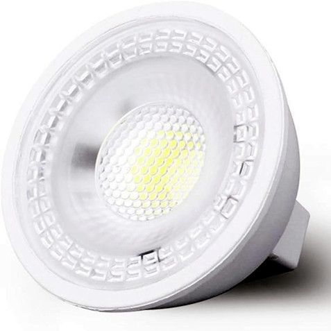
As shown in Figure 5-9, LEDER Lighting's OHW fanless cooler utilizes synthetic jet design, requiring much less current than a typical motor and operating on a 5V power supply. The cooler employs an electromagnetic-coupled diaphragm, which oscillates the diaphragm at speeds of 100-200 cycles per second through electromagnetic drivers, pulsing high-speed air jets through tiny nozzles. Once the gas exits the nozzle, it entrains the surrounding air, similar to how a tornado entrains the air around it. Standard products come in two structures: one resembling an MR-16 lamp, and the other similar to a PAR-38 lamp base. MR-16 and PAR-style structures of heat sinks are suitable for 20W and 50W LED luminaires.
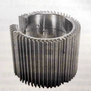
Figure 5-9 Fanless cooler
When replacing incandescent and CFL energy-saving lamps with LED light bulbs, people hope to use LED bulbs in their existing traditional sockets. However, luminaire designers should not be bound by traditional luminaire design concepts. In fact, old-style light sockets are not ideal for installing LED light bulbs. LED luminaire design should prioritize heat dissipation and then luminaire aesthetics. As shown in Figure 5-10, the OHW second generation series LED light produced by LEDER Lighting Manufacturer is an example. The heat sink of this downlight can ensure that the LED junction temperature remains below 35°C and offers a 7-year warranty. It has a design life of 80,000 hours, a power rating of 15W, a color temperature of 4100K, and an efficacy of 73 lm/W.
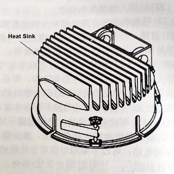
Figure 5-10 15W LED downlight
(4) Separate the LED Driver from the LED Fixture
The heat generated by the LED lighting power supply itself can increase the temperature rise of the LED lamp. Integrating the power supply with the LED lamp can result in uneven heating of the entire lamp, making it susceptible to fatigue and early failure. When the power supply is separated, the temperature distribution across the entire fixture becomes uniform.
(5) PCB Heat Dissipation Design
For LED devices with small differences in thermal resistance, choosing different PCB design approaches can have a significant impact on the final system's thermal resistance, subsequently affecting the system's temperature. In addition to this, factors such as the material, thickness, area of heat-dissipating materials, and the treatment of the heat-dissipating interface, soldering methods, and soldering conditions are all considerations that lighting fixture manufacturers need to take into account.
(6) Use a Temperature Control Circuit to Limit LED Temperature Rise
In LED luminaire systems, a temperature control circuit can be added to limit the temperature rise of the LED. When the LED temperature exceeds a set threshold, the temperature control circuit activates, causing the driver power supply to output at an appropriate lower level. When the temperature decreases to a certain value, the driver circuit returns to its normal operating state.
Figure 5-11 shows the schematic diagram of a temperature control circuit in a constant current LED driver power supply. The AC input voltage for the LED luminaire's offline driver power supply is 220V, and the DC output current is adjustable between 1.21.7A, with adaptive output voltage (3639V). In the temperature control circuit, RP is an adjustable resistor, KT is a temperature relay with normally open contacts, closing at 56°C, and opening at 45°C, and RT is an NTC thermistor. The contacts of the temperature relay KT and the NTC thermistor RT are both installed on the LED module and are in close contact with the module.
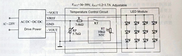
Figure 5-11 LED lamp constant current drive power supply temperature control circuit
At room temperature, KT is in the open state, and RP controls the output current to be set at 1.6A. When the relay temperature reaches 56°C, KT automatically closes, and the temperature control circuit starts working to reduce the output current (IOUT<1.35A). When the relay temperature drops to 45°C, KT automatically opens, and the driver power supply circuit returns to normal operation, dissipating heat to the atmosphere through the LED module heatsink.
In summary, the commonly used thermal interface materials in LED lighting fixtures can be categorized based on their roles in the fixture as structural thermal interface materials and filler thermal interface materials. Structural thermal interface materials not only serve as the housing of the fixture but also contribute to the heat dissipation of LED light sources, such as thermal conductive plastics, among others. On the other hand, filler thermal interface materials are primarily used between the heat-generating component and the heat sink to facilitate thermal conduction between the two. Since the thermal conductivity of thermal interface materials is relatively low compared to heat-generating elements and metal heat sinks, the choice of thermal interface material is crucial as it determines the speed of heat transfer.
(1)Thermal Conductive Double-Sided Tape:
Thermal conductive double-sided tape is typically used between the aluminum base of a metal core printed circuit board (MCPCB) and the heat sink. It is used to secure the aluminum base to the heat sink. Its advantages include easy installation and low cost. However, its thermal conductivity is not very high, making it suitable for applications like fluorescent lamps and spotlighting.
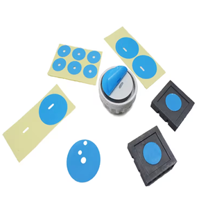
1 Thermal Conductive Double-Sided Tape
(2)Thermal Conductive Silicone Grease:
Thermal conductive silicone grease is applied between the LED aluminum substrate and the heat sink. It offers good thermal conductivity, can be applied thinly, and is suitable for smaller surface area products such as LED spotlights, LED floodlights, UFO high bay lights, LED fountain lights, LED ground lights, and LED streetlights. It can experience silicone bleeding, drying, and lens contamination at high temperatures.
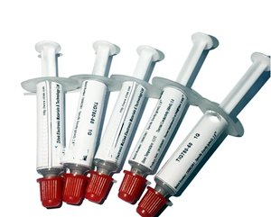
2 Thermal Grease
(3)Thermal Conductive Graphite Sheets:
Thermal conductive graphite sheets are reasonably priced high-performance thermal interface materials. Their unique crystal grain orientation and sheet-like structure allow them to closely conform to different contact surfaces, resulting in excellent heat conduction. They are used between the LED aluminum substrate and the heat sink and offer good thermal conductivity. They are commonly used in applications like streetlights, spotlights, and LED TVs.
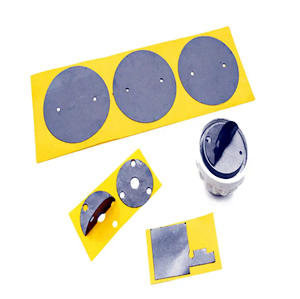
3 Thermal Conductive Graphite Sheet
(4)Thermal Conductive Plastic:
Thermal conductive plastic, typically made from nylon, is a thermal engineering plastic developed for use in ordinary-looking structural components. It combines excellent thermal conductivity with a good heat transfer rate and can be matched with common engineering plastics. It reduces the weight of aluminum components by up to fifty percent. It is easy to mold in injection molds and is used to create LED light housings, such as solar street lights, solar floodlights and solar ceiling lights.
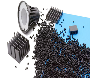
4 Thermal Conductive Plastic
We invite you to experience the difference that our LED lamps can make in your client’s home, office, or any other space you choose to illuminate. Enjoy the peace of mind that comes with knowing you have invested in high-quality lighting solutions that prioritize performance and longevity.
If you have any questions or would like to explore our range of LED lamps further, please do not hesitate to reach out to our dedicated customer support team. We are always here to assist you in finding the perfect lighting solutions for your needs.
Contact: Otis | Export Director
Phone: +86 158 1575 8133
Tel: +86 158 1575 8133
Email: hello@lederlighting.com
Add: No. 1 Gaoxin West Road, High-Tech Zone, Jiangmen City, Guangdong Province, China