Welcome: Jiangmen LEDER Lighting Co., Ltd.

Secondary optical design is in contrast to primary optical design. The primary optical design of LEDs focuses on enhancing the light emission efficiency of LEDs by working with the shape of the encapsulation material. The primary optical system of LEDs includes components like the resin lens and internal reflectors. Primary optical design for LEDs is mainly divided into three methods: refraction, reflection, and refraction-reflection.
In the case of refraction, as shown in Figure 5-12, light emitted from the LED chip refracts on the surface of the shell. In this propagation mode, around 70% to 80% of the light leaks from the sides of the encapsulation material, and the solid angle covered by the light concentration surface is limited, resulting in low concentration efficiency.
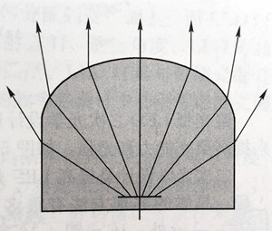
Figure 5-12 Refractive LED housing package
Reflective LED encapsulation structures are divided into two types: backward reflection and forward reflection, as shown in Figure 5-13. The solid angle covered by the light concentration surface is larger in reflective designs, leading to higher concentration efficiency.
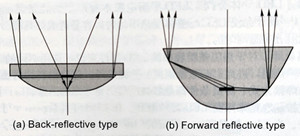
Figure 5-13 Reflective LED housing package
Refraction-reflection LEDs add a refractive surface to the forward reflection structure, enhancing light concentration and, consequently, improving concentration efficiency.
Secondary optical design aims to increase the effective light utilization of luminaires. Traditional light source fixtures have relatively low light utilization because traditional light sources emit light in all directions, with some of the light blocked by the light source itself. Additionally, traditional light sources have large emission points, making optical design challenging and resulting in inefficient fixtures. LED light sources approximate point sources and exhibit directionality. Leveraging these two characteristics is crucial in luminaire optical design. Through LED array design and secondary optical design, LED luminaires can achieve relatively ideal light distribution curves.
The importance of luminaires in various lighting scenarios is self-evident. The primary function of luminaires is to provide electrical connections to light sources. In general, users are most concerned about whether a luminaire can illuminate the desired area and create a comfortable environment. However, for professional lighting designers, in addition to being well-versed in the selection of luminaire materials, lenses, and reflector systems, they must also understand the luminous intensity distribution curve of the luminaire. This allows them to assess the quality of the light pattern projected by the luminaire, calculate the luminaire's efficiency, and determine the illuminance values at arbitrary points within a space. With this information, they can also calculate the distribution of illuminance within a spatial area. Therefore, it is not an exaggeration to say that the luminous intensity distribution curve of a luminaire is its lifeline. Understanding this lifeline is a crucial skill for lighting designers. Here, we will explore what the luminous intensity distribution of LED indoor lighting &outdoor lighting luminaires entails.
For spotlight-type LEDs, when it is necessary to achieve wide-area illumination or displays, a diffusion plate can be added to accomplish this. The principle of a diffusion plate is similar to that of cylindrical and trapezoidal prism sheets, as shown in Figure 5-14. Cylindrical prism sheets (see Figure 5-14 (a)) mainly extend the beam angle in one direction, providing uniform illumination and are suitable for signal lights. Trapezoidal prism sheets (see Figure 5-14 (b)), while also extending the beam angle in one direction, have a different light intensity distribution compared to cylindrical prism sheets. Both of these diffusion plates are one-dimensional; if diffusion is required in two directions, diffusion plates for both directions need to be used, or a combined plate can be employed.
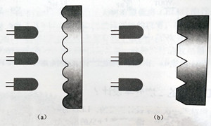
Figure 5-14 Schematic diagram of scattering secondary optical design
The secondary optical design for spotlight-type LEDs enhances their focusing capabilities and light intensity by adding lenses or lens arrays, as shown in Figure 5-15.
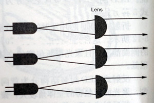
Figure 5-15 Schematic diagram of secondary optical design of concentrated LED
Secondary optical design is a necessary means to improve the effective light utilization of LED luminaires, and there are many methods to achieve it. In addition to LED prism sheets and LED + lenses, there are LED reflector cups, LED + reflector cups + lenses, and projection methods that divide single LED module projection and multiple LED module area projection, as shown in Figure 5-16.
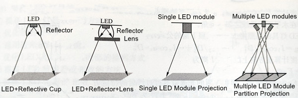
Figure 5-16 Schematic diagram of secondary optical design implementation
In LED secondary optical design, high light transmittance lenses should be selected to improve luminaire efficiency. Light transmittance is an important technical parameter of LED lenses, representing the ratio of the light flux on the target surface to the total light flux emitted by the LED light source. Light emitted by LEDs experiences three types of losses when passing through a lens: light reflected from the top surface of the lens, light absorbed by the lens, and light refracted through the side of the lens, as shown in Figure 5-17. Currently, well-known manufacturers produce lenses with a light transmittance of only about 89%, which means that more than 10% of the total light flux emitted by the LED is lost in the lens. To ensure that LED luminaires have better optical characteristics, besides requiring high light transmittance in lenses, factors such as illuminance uniformity, operating temperature range, resistance to ultraviolet radiation, and yellowing rate should also be considered.
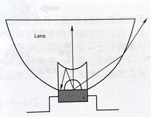
Figure 5-17 Lens light distribution diagram
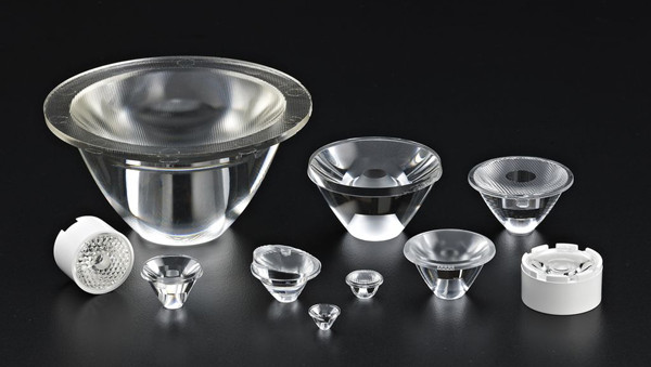
I'd like to randomly share with you some optical lenses that we use from our material warehouse.
|
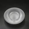
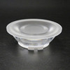
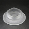
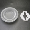
75mm ultra-thin anti-glare lens ultra-thin series optical lens for wall washer track lighting |
||||
|
|
|
|
|
|
(1). Crafted from high-quality Japanese PC raw materials and utilizing high-precision aspherical optical processing along with imported mold steel, this lens boasts a low shrinkage rate. It is a cutting-edge, versatile, energy-efficient, and environmentally friendly material.
(2). The lens offers precise angles, high central light intensity, excellent light focusing, uniform light distribution, and no secondary light spots. It boasts a low anti-glare index and eliminates shadows.
(3). Notable features of this lens include high-temperature resistance, exceptional transparency, lightweight construction, impact resistance, heat insulation, flame retardancy, and resistance to aging. It also incorporates several pillars at the bottom for secure attachment to the lamp board, enhancing lamp production efficiency.
(4). This lens is compliant with SGS certification and adheres to ROHS environmental requirements.
Due to the fact that LEDs are close to being theoretical "point sources of light," precise positioning of the light-emitting point is achievable in optical system design. This solves issues of light source concealment and luminaire diversity. The characteristics of LED light sources create significant flexibility in optical design and luminaire design. For instance, in general lighting, where high brightness is required, linear LED strips can be used along with high-transmittance lampshades to improve luminous efficiency. The use of light guide plate technology can transform an LED point light source into a surface light source, improving uniformity while preventing glare. For some accent and layered lighting, spotlighting effects are needed, and specific spotlight lenses can be chosen to meet optical requirements. Additionally, luminaires like road lighting and traffic signal lights have specific requirements for their luminous intensity distribution curves, which require special considerations in LED secondary optical design.
Traditional light source luminaires typically use a reflector to evenly distribute the luminous flux of a single light source onto the illuminated surface. In contrast, LED luminaires consist of multiple LED chips, and by designing various factors such as the illumination direction, mirror angles, and relative positions of LED arrays for each LED, it is possible to provide the illuminated surface with uniform and desired illuminance. The optical design of LED luminaires differs from traditional light source luminaires, and maximizing the efficiency of LED luminaires using the characteristics of LED light sources is a key factor to consider in the design.
(1) Illuminance Calculation for LED Luminaires
Illuminance, denoted as E, is the luminous flux received per unit area on the surface being illuminated. It is measured in lux (lx). Preliminary simulated illuminance calculations during luminaire design are crucial steps in LED luminaire photometric design. The objective is to compare actual requirements with the results of simulated calculations, taking into account luminaire shape, heat dissipation, and other conditions, to determine LED types, quantity, arrangement, power, and lenses.
Since LED luminaires often contain several dozen or even over a hundred LEDs, for multiple "point light sources" arranged together, point-by-point calculation methods are used to calculate illuminance. This involves calculating illuminance for each LED calculation point and then adding them up to obtain the total illuminance. The illustration in Figure 5-18 shows a schematic of point-by-point illuminance calculation. In the diagram, D represents the distance between the light source and the illuminance calculation point, I is the light intensity of the light source in the direction of the illuminance calculation point, and α is the angle between the line connecting the light source to the point being illuminated and the perpendicular line to the horizontal plane.
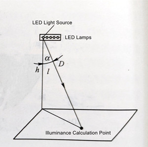
Figure 5-18 Schematic diagram of point-by-point illumination calculation
The total illuminance, E_total, for LED luminaires can be calculated according to the following formula:
E_total = (I_1 * COSα_1 / D^2_1) + (I_2 * COSα_2 / D^2_2) + ... + (I_n * COSα_n / D^2_n)
Remark:
I represents the light intensity in the direction of the illuminance calculation point.
Eff represents lens efficiency, i.e., the light intensity value in a specific direction after passing through the lens for each lumen (can be found in the lens's photometric curve).
φ represents the total luminous flux emitted by the LED.
(2) Light Source Luminous Efficiency, Luminaire Efficiency, Optical Efficiency, and Lighting System Luminous Efficacy
In practice, what users care about is the illuminance on the actual area or space that needs to be illuminated. Light source luminous efficiency, luminaire efficiency, and optical efficiency are all concepts related to the lighting system luminous efficacy, as shown in Figure 5-19.
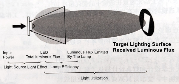
Figure 5-19 Schematic diagram of light source efficiency, lamp efficiency and light utilization rate
The light source luminous efficiency (η_LED) is the ratio of the luminous flux (φ_LED) of the LED light source to the electrical power consumed by the LED (P_LED). In other words, η_LED = φ_LED / P_LED.
Luminaire efficiency (η_luminaire) is the percentage of emitted luminous flux (φ_emitted) of the luminaire to the LED luminous flux (φ_LED). Therefore, η_luminaire = (φ_emitted / φ_LED) * 100%.
Optical efficiency (η_utilization) is the percentage of luminous flux (φ_utilized) within the effective area of the illuminated object to the LED luminous flux (φ_LED). So, η_utilization = (φ_utilized / φ_LED) * 100%.
In the LED lighting system shown in Figure 5-20, the light emitted by the light source is projected onto the target illuminated area after luminaire photometry, resulting in a circular light spot. However, users require illumination on a rectangular area. Based on this figure, LED light source luminous flux φ_LED = 1000lm, power P_LED = 15W, luminous flux φ_utilized within the effective illumination area is 450lm, and luminaire-emitted luminous flux φ_emitted = 650lm. Using this data, we can calculate:
LED light source efficiency η_LED = 1000lm / 15W ≈ 67 lm/W
Luminaire efficiency η_luminaire = (650lm / 1000lm) * 100% = 65%
Optical efficiency η_utilization = (450lm / 1000lm) * 100% = 45%
In a typical LED lighting system, which consists of LED array light sources, driver circuits, lenses, and heat sinks, when considering the driver circuit's efficiency η_circuit, the system luminous efficacy η_system can be calculated using the following formula:
η_system = η_LED * η_circuit * η_utilization
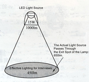
Figure 5-20 Schematic diagram of point-by-point illumination calculation
(3) Methods to Improve LED Luminaire Efficiency and Lighting System Luminous Efficacy
① Methods to Improve LED Luminaire Efficiency:
a. Optimize heat dissipation design.
b. Use lenses with high light transmittance.
c. Optimize the arrangement of LEDs inside the luminaire.
② Methods to Improve LED Lighting System Luminous Efficacy:
a. Increase the light efficiency of LED light sources. Besides choosing high-efficiency LED light sources, ensure good heat dissipation of luminaires to prevent a significant drop in light output due to high LED temperature during operation.
b. Select an appropriate topology for LED lighting power supplies to ensure the highest possible operating efficiency while meeting specific electrical and driving requirements.
c. Use reasonable luminaire structures and optical designs to ensure the highest optical efficiency (i.e., light utilization efficiency).
The total luminous flux of LED lighting fixtures is not only related to the luminous intensity and drive current of the LED but also closely connected to the transmittance of the LED lens. The LED lens not only affects the light output of the luminaire but is also inseparable from the formation of the light spot on the illuminated surface. In simple terms, an LED lens is a lens that is closely related to and associated with LEDs. Other lenses such as those used in lighting devices, telescopes, etc., are not within the scope of this explanation. LED lenses and reflector cups are mainly used for the focusing and light guidance of LED cold light source products. High-power LED lenses are designed with different photometric curves based on the angles at which LED emits light. This is achieved by increasing optical reflection, reducing light loss, and improving efficiency (using specially designed aspherical optical lenses).
Please note that this explanation primarily focuses on the role and significance of LED lenses in relation to LED lighting fixtures and their light output.
Silicone Lens: Silicone lenses are commonly used because they have good heat resistance (suitable for reflow soldering) and are often directly encapsulated with LED chips. Silicone lenses are relatively small, with diameters ranging from 3 to 10mm.
PMMA Lens: PMMA, also known as Polymethyl Methacrylate, or acrylic glass, is an optical-grade material used for lenses. It offers advantages such as high production efficiency (can be injection-molded), high light transmittance (approximately 93% with a 3mm thickness), but has limitations in terms of temperature resistance (up to 70°C, with a heat distortion temperature of 90°C).
PC Lens: PC, or Polycarbonate, is another plastic material used for lenses. It offers high-temperature resistance (above 130°C), and it can also be injection-molded for efficient production. However, its light transmittance is slightly lower (around 87%) compared to PMMA.
Glass Lens: Glass lenses are made from optical glass materials and are known for their high light transmittance (97%) and excellent temperature resistance. However, they are fragile, and achieving non-spherical surface accuracy can be challenging. Glass lenses also have lower production efficiency and tend to be more costly.
These are some of the common materials used for LED lenses, each with its own set of advantages and limitations. The choice of material depends on the specific requirements of the LED application and the desired optical properties.
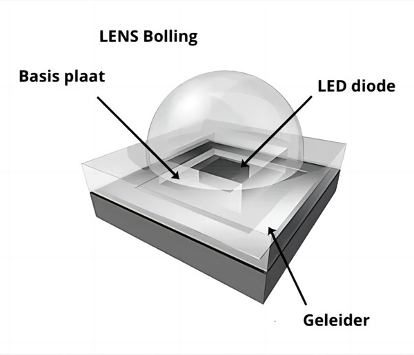
(1)Primary Lens
① Primary lenses are directly encapsulated or adhered to the LED chip's holder, forming a single unit with the LED.
② LED chips theoretically emit light in a 360° angle, but in practice, when placed on an LED holder and encapsulated, the maximum emitting angle of the chip is 180°. Additionally, there may be some scattered light from the chip. Primary lenses effectively collect all the light and can provide desired emitting angles such as 160°, 140°, 120°, 90°, or even 60°.
③ Primary lenses are often made of materials like PMMA or silicone.
(2)Secondary Lens
① Secondary lenses are separate objects from the LED but are closely integrated with it in applications.
② The primary function of secondary lenses is to refocus the wide-angle light emitted by the LED (typically 90° to 120°) into a specific desired angle ranging from 5° to 80°. This narrowing of the beam angle significantly increases the illuminance.
③ Secondary lenses are commonly made from materials like PMMA, PC, or glass.
These distinctions in lens types are based on how they are integrated with LEDs and their specific functions in controlling the light distribution. The choice of lens type depends on the lighting requirements and desired beam angles for a particular LED application.
(1)Through-Type Lens (Convex Lens)
① When LED light passes through one surface of the lens (a double-convex lens has two curved surfaces), it undergoes refraction, resulting in a focusing effect. Adjusting the distance between the lens and the LED will change the angle (inversely proportional). Curved surfaces designed using aspherical techniques can produce very uniform light patterns. However, due to limitations in the lens diameter, some light from the sides of the lens remains unused, leading to inevitable light leakage. Currently, optical technology has not provided a feasible solution to this issue.
② Generally used for wide-angle (40° to 80°) focusing applications, such as desk lamps, streetlights, indoor lighting fixtures, etc.
(2)Total Reflection Lens (Conical or Cup-Shaped)
① The lens design utilizes through-type focusing at the front while the conical surface can collect and reflect all the side light outward. The overlap of these two types of light (with nearly the same angles) results in the most efficient light utilization and beautiful light patterns.
② Changes can be made to the conical lens surface, such as designing it as a mirror surface, frosted surface, bead surface, striped surface, threaded surface, convex surface, or concave surface, to achieve different light pattern effects.
(3)LED Lens Module (Multi-Head Lens)
① This involves creating a multi-head lens module by injecting multiple individual lenses into a single unit. Depending on specific requirements, lens modules can be designed as 3-in-1, 5-in-1, or even 10-in-1 modules.
② This design effectively saves production costs, ensures product consistency in quality, saves structural space in lighting fixtures, and makes it easier to achieve features like "high power."
These different types of lenses are designed to meet various lighting needs and are selected based on the desired light distribution and beam angle for specific LED applications.
In this discussion, we emphasize the paramount significance of primary and secondary optical material selection, along with the key technical assessment points for lighting designers. Specifically, we delve into the critical aspects of reducing lumen degradation over time and managing color temperature fluctuations.
The primary aim of this article is twofold: firstly, to raise awareness among lighting designers regarding these crucial considerations, and secondly, to prompt international LED procurement companies to recognize the pressing need for continual enhancement of optical materials. To achieve this, it is imperative for these companies to closely monitor their OEM (Original Equipment Manufacturer) suppliers and designate them as pivotal points of evaluation. By doing so, they can effectively steer the ongoing advancement of material development in the realm of LED lighting.
By reinforcing the importance of these factors, we aim to foster a collaborative effort within the industry, ultimately leading to superior and more reliable LED lighting solutions.
Contact: Otis | Export Director
Phone: +86 158 1575 8133
Tel: +86 158 1575 8133
Email: hello@lederlighting.com
Add: No. 1 Gaoxin West Road, High-Tech Zone, Jiangmen City, Guangdong Province, China