Welcome: Jiangmen LEDER Lighting Co., Ltd.


Street lighting plays a crucial role in enhancing safety and visibility in both urban and suburban areas, making it an integral part of modern infrastructure. To meet the growing demand for energy-efficient and environmentally friendly lighting solutions, LED streetlights have become the preferred choice for municipal authorities and city planners. These lights not only provide excellent illumination but also significantly reduce energy consumption and maintenance costs. A key component in the operation of LED streetlights is the LED driver, which ensures that the LEDs receive the correct power and control signals for optimal performance. Therefore, as professionals in the LED lighting industry, it is essential to have a deeper understanding of these components.
In this design guide, we will delve into the intricacies of the LED drivers used in streetlights, with a focus on three key components: FAN7554, NCP1652, and PLC810PG controllers. We will explore their pin functions, features, and applications, elucidating how these components enhance the efficiency and reliability of LED street lighting systems.
As we delve into the technical details of these LED drivers, we will also examine the principles of operation of the LLC resonant converter and the structural elements of the PLC810PG controller. After reading this guide, you will have a comprehensive understanding of LED driver design for streetlights and the critical considerations to ensure optimal performance.
The pin functions of FAN7554 are as follows:
Pin 1 (FB): Inverted input of the PWM comparator, also used for ON/OFF control and Over Power (OLP) detection.
Pin 2 (S/S): Soft start.
Pin 3 (IS): In-phase input of the PWM comparator, used for overcurrent detection.
Pin 4 (RT/CT): Oscillation frequency setting.
Pin 5 (GND): Internal logic ground.
Pin 6 (OUT): Drive voltage output.
Pin 7 (VCC): IC operational power supply input.
Pin 8 (VREF): 5V reference voltage output.
The internal functional block diagram of FAN7554 is shown in Figure 7-29. From the pin diagram and internal functional block diagram, it can be observed that the functions of FAN7554 are essentially similar to UC284X, with the addition of features like soft start.
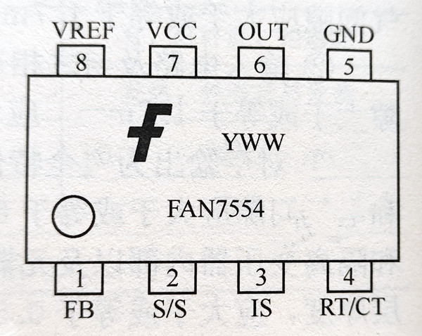
Figure 7-28: Pin Arrangement of FAN7554
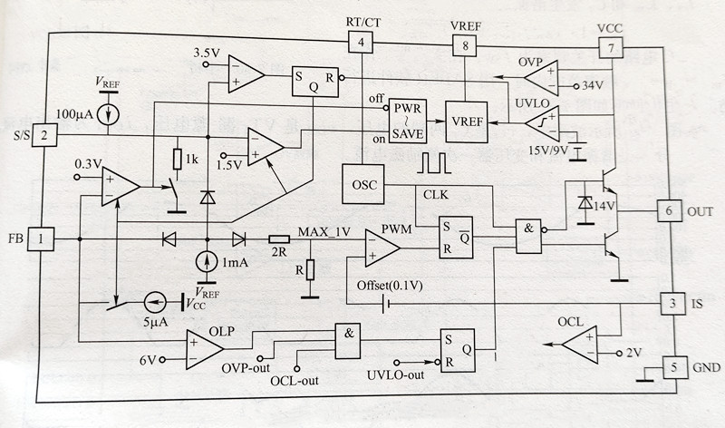
Figure 7-29: Internal Functional Block Diagram of FAN7554
The characteristics of a 90W LED streetlight driver power supply based on the NCP1652 are as follows:
The NCP1652 is a highly integrated controller designed for implementing PFC (Power Factor Correction) and isolation in a single-stage buck-type DC/DC converter. It offers a cost-effective solution with reduced component count. This controller is particularly suitable for notebook adapter battery chargers and offline applications, with an ideal power range between 75W to 150W. The single-stage configuration is based on a flyback converter and operates in either Continuous Conduction Mode (CCM) or Discontinuous Conduction Mode (DCM).
The NCP1652 is an efficient system integrator and includes a second adjustable delay driver, which can be used for synchronous rectification control on the secondary side, active clamp on the primary side, or other applications. Additionally, the controller features a patented "soft skip" characteristic to reduce audio noise during light load conditions. The NCP1652 also incorporates a high-voltage startup circuit, voltage feedforward, brownout detection, built-in overload timer, input lockout, and high-precision multiplier.
The PLC810PG single-chip control chip from IR (International Rectifier) is an integrated control solution that combines a half-bridge driver with PFC (Power Factor Correction) and LLC (Inductor-Inductor-Capacitor) resonant converter topologies. This controller is suitable for a range of applications, including LED streetlights in the power range of 50W to 600W, LED TV power supplies in the range of 32 to 60 inches, as well as PC main power supplies and workstation power supplies.
The working principle of an LLC resonant converter is as follows:
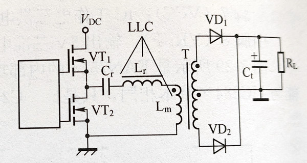
When the output power of the power supply exceeds 150W, the half-bridge LLC series/parallel resonant converter topology offers many advantages over a single-switch flyback converter topology. The basic circuit structure of a half-bridge LLC resonant converter is shown in Figure 7-30.
The operating principle of the LLC circuit topology is as follows:
In Figure 7-30, VT1 and VT2 are the upper and lower switches of the half-bridge, L is the resonant inductor, C1 is the resonant capacitor, and Lm is the transformer magnetizing inductance. Lr, Lm, and Cr together form the LLC resonant network, with Cr also serving as a DC-blocking capacitor.
The LLC resonant converter (referred to as LLC) has two intrinsic resonant frequencies. The resonance frequency fr, occurring between Lr and Cr, is given by:
fr = 1 / (2π√(Lr * Cr))
The resonance frequency fm, occurring between Lr, Lm, and Cr, is given by:
fm = 1 / [2π√((Lr + Lm) * Cr)]
The switching frequency of the LLC circuit is denoted as fsw. When the converter operates in the frequency range where fm < fsw < fr, the main waveforms during simulation using SABER software are as shown in Figure 7-31.
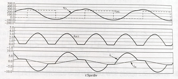
In the waveforms shown in Figure 7-31, vCr represents the voltage across Cr, vDSL is the drain-source voltage of VT1, iOUT is the output current, ir and im are the resonant current and transformer primary-side magnetizing current, respectively.
The operation of the circuit can be divided into the following two stages:
Energy Transfer Stage: During this stage, Lr and Cr carry sinusoidal currents, and ir > im. Energy is transferred through the transformer to the secondary side.
Reset Stage: When ir = im, energy transfer from the primary to the secondary ceases. Lr, Lm, and Cr resonate, and the entire resonant circuit exhibits high impedance, causing the primary-side current to decrease relatively slowly.
By careful design, the half-bridge MOSFETs can be zero-voltage switched, and the current in the transformer's secondary-side rectifier diode can be reduced to zero at ir = im, achieving zero-current turn-off. This helps reduce switching losses and improves the efficiency of the converter. The LLC converter is advantageous when operating in the frequency range of fm < fsw < fr. In practical LLC circuits, Lr is often merged into the primary winding of the transformer, and the resonant circuit consists of only Cr and the transformer's primary-side magnetizing inductance.
The PLC810PG chip is composed of several parts, each serving a specific function. Here is an explanation of each part:
(1) PFC Controller:
The PFC controller in the PLC810PG chip is a Continuous Current Mode (CCM) PFC controller with only four pins (excluding the ground pin), making it one of the controllers with the fewest pins. This type of PFC controller is primarily composed of components such as an Operational Transconductance Amplifier (OTA), discrete Voltage-Programmable Gain Amplifier (DVGA), low-pass filter (LPF), PWM circuit, PFC circuit, MOSFET driver (output on pin GATEP), and protection circuitry. The PFC controller has two input pins, namely ISP (pin 3) and FBP (pin 23).
Pin FBP is the feedback input for the DC output voltage of the PFC boost converter and is connected to the in-phase input of the OTA. The output of the OTA can be seen as an input to the equivalent multiplier in the PFC controller. The output at pin VCOMP of the OTA is connected to the frequency compensation element. The feedback loop is responsible for PFC output voltage regulation and overvoltage and undervoltage protection. The internal reference voltage VFBPREF at pin FBP of the PLC810PG is 2.2V. If the voltage at pin FBP (VFBP) exceeds VovH = 1.05 × 2.2V = 2.31V, the PLC810PG provides overvoltage protection and interrupts the output at pin GATEP. If the voltage falls below VFBP < VIN = 0.23 × 2.2V = 0.506V, the PFC circuit is disabled. If VEBP < VsDL = 0.64 × 2.2V = 1.048V, the LLC stage will be turned off.
(2) LLC Controller:
The FBL pin of the half-bridge LLC resonant controller is the reverse voltage input. The higher the current flowing into the FBP pin, the higher the switching frequency of the LLC converter. The maximum switching frequency of the LLC stage is set by a resistor connected between the FMAX pin and the VREF pin (3.3V), and it can reach 2 to 3 times the normal operating frequency (100kHz). The FBL pin also provides overvoltage protection. The ISL pin (pin 22) is the current sensing input for the LLC stage, providing both fast and slow (8 clock cycles) two-level current protection. The dead-time circuit ensures that the external MOSFETs do not turn on simultaneously and achieves Zero Voltage Switching (ZVS).
PFC and LLC frequencies and phases are synchronized, reducing noise and EMI. The PFC circuit does not require AC input voltage sensing as a control reference, which is a distinguishing feature from other similar controllers. The VCC pin (pin 7) of the PLC810PG has a turn-on threshold of 9.1V and an undervoltage shutdown threshold of 8.1V. The VCC voltage can be selected between 12V and 15V.
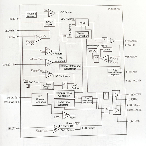
Figure 7-32: PLC810PG Functional Block Diagram
The 150W LED street light driver power supply circuit using the PLC810PG controller is shown in Figure 7-33. The circuit has an AC input voltage range of 140-265V, a DC output of 48V/3.125A, a power factor (PF) greater than or equal to 0.97, and a system total efficiency of over 92% at full load. Both the PFC stage and LLC stage have efficiencies exceeding 95%.
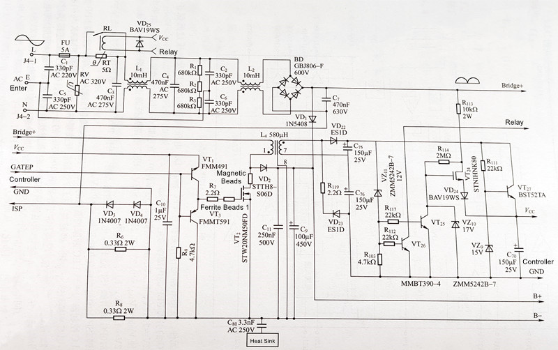
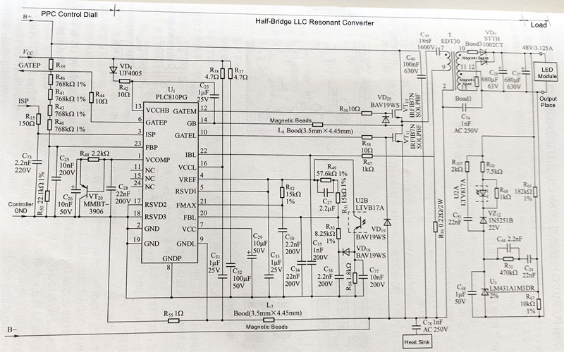
Figure 7-33: 150W LED Street Light Driver Power Supply Circuit with PLC810PG Controller
Those involved in the lighting industry should be well aware that efficiency, longevity, and environmental sustainability are of paramount importance in the realm of LED street lighting. As cities and municipalities strive to reduce energy consumption and light pollution, LED street lights have emerged as a smart and environmentally friendly solution. However, behind the brilliance of these lights lies a complex network of components, with the LED driver being the linchpin of the system.
In this guide, we delve deep into the fundamental components of an LED driver, which include the FAN7554, NCP1652, and PLC810PG controllers, each with its own unique capabilities and applications. We also elucidate the working principle of the LLC resonant converter and unravel the intricate circuit structure of the PLC810PG controller.
Designing and implementing LED drivers for street lights is a complex endeavor, but armed with the right knowledge and components, it is possible to create lighting systems that not only meet contemporary needs but also contribute to a greener, more sustainable future. Whether you're an engineer, designer, or simply someone interested in the technology that illuminates our streets, this guide serves as a valuable resource for comprehending and designing LED drivers that light the path forward.
LEDER Lighting is a highly professional LED street light manufacturer, and we are committed to resolving your issues and enhancing the success rate of your lighting project.
Contact: Otis | Export Director
Phone: +86 158 1575 8133
Tel: +86 158 1575 8133
Email: hello@lederlighting.com
Add: No. 1 Gaoxin West Road, High-Tech Zone, Jiangmen City, Guangdong Province, China