Welcome: JiangMen Leder Lighting Co,, Ltd


The materials and components for the secondary heat dissipation design of LED luminaires mainly include heat dissipation boards, bonding materials, and heat dissipation devices.
The role of the heat dissipation board is to connect with the internal heat sink of the LED, conduct and dissipate heat, and solve the problem of independent electrical circuit connections and heat dissipation channels between individual LEDs. There are two types of heat dissipation boards: metal PCB and metal-based composite materials. Common metal PCBs include metal low-temperature co-fired ceramic substrates, which have the advantage of lower cost but may suffer from issues like high thermal expansion coefficients and relative density. Metal-based composite materials are an improved version of metal PCBs, offering high thermal conductivity, lower relative density, and adjustable thermal expansion coefficients.
There are three types of bonding materials used for bonding LED chips to the heat sink: thermal conductive adhesive, conductive silver paste, and tin paste. Thermal conductive adhesive has a curing temperature below 150°C, low thermal conductivity, and relatively poor heat conduction properties. Conductive silver paste has a curing temperature below 200°C and offers good thermal conductivity and bonding strength. Tin paste has better thermal conductivity than the other two bonding materials and also exhibits good conductivity, making it widely used.
The principles for selecting heat sink materials are as follows:
(1).Good thermal conductivity.
(2).Easy to process, good ductility, and relatively stable at high temperatures.
(3).Relatively low cost and easy procurement.
(4).Currently, heat sink materials are all made of metal.
Table 7-12 provides some commonly used materials and their thermal conductivity values.
Table 7-12: Commonly Used Heat Sink Materials and Thermal Conductivity
|
Metallic Material |
Thermal Conductivity/[W/(m.K)] |
Metallic Material |
Thermal Conductivity/[W/(m.K)] |
|
Gold |
317 |
AA6061 Aluminum Alloy |
155 |
|
Silver |
429 |
AA6063 Aluminum Alloy |
201 |
|
Copper |
401 |
ADC12 Aluminum Alloy |
96 |
|
Aluminum |
237 |
AA1070 Aluminum Alloy |
226 |
|
Iron |
48 |
AA1050 Aluminum Alloy |
209 |
luminum, as the most abundant metal in the Earth's crust, is favored for heat sink manufacturing due to its high thermal conductivity, low density, and affordability. However, pure aluminum is relatively soft, so it is often alloyed with various materials to create aluminum alloys that possess characteristics not found in pure aluminum. Different aluminum alloys are used in various applications, depending on their specific properties and processing methods.
Among the five different aluminum alloys listed in Table 7-12, AA6061 and AA663 are preferred for heat sink manufacturing due to their excellent thermal conductivity and processing capabilities. They are suitable for extrusion processes and are commonly used in heat sink production. ADC12 is suitable for die casting but has lower thermal conductivity, so in heat sink manufacturing, AA1070 aluminum alloy is often used as a replacement. AA1050, on the other hand, has good ductility and is suitable for stamping processes, often used to manufacture thin sheets.
To enhance heat dissipation, increasing the contact area between the heat sink surface and air is crucial. The external surface of the heat sink can be designed with fins. Fins come in various shapes, and their quantity, position, size, angle of inclination, and thickness all require careful consideration. In addition to the common straight-line fins, there are wavy fins, spiral fins, cylindrical fins, and conical fins, among others. These various designs aim to facilitate airflow and rainwater runoff, optimizing heat dissipation.
The primary manufacturing process for heat sinks is aluminum extrusion, as shown in Figure 7-19. Aluminum extrusion technology is relatively simple and suitable for large-scale production. The efficiency of an aluminum extrusion heat sink is often measured by the ratio of the height of the fins (referred to as "Pin") to the distance between adjacent fins (referred to as "Fin"). The higher this "Pin-Fin ratio," the larger the effective heat dissipation area of the heat sink, indicating more advanced extrusion technology. High-end heat sinks can achieve Pin-Fin ratios as high as 18.
Figure 7-19: Heat Sink Manufactured via Aluminum Extrusion Process
Heat sinks can also be manufactured using cutting processes. Cut heat sink fins are thin and closely spaced, increasing the heat dissipation area, as shown in Figure 7-20. However, the cutting process requires advanced technical skills and presents machining challenges, so it is generally less commonly used.
Figure 7-20: Heat Sink Manufactured via Cutting Process
To ensure that the heat sink meets the requirements of rapid heat absorption, low thermal resistance, and efficient heat dissipation, it is not only necessary to demand excellent heat sink performance but also requires a tight and seamless connection between the heat-absorbing base of the heat sink and the LED module. Additionally, the heat-absorbing base should have sufficient thickness to enhance lateral heat conduction capability.
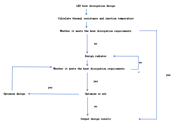
Figure 7-21 illustrates the process of secondary heat dissipation design for LEDs. During the secondary heat dissipation design, the first step involves calculating thermal resistance and junction temperature to determine if they meet the LED's heat dissipation requirements. If the requirements are met, the results are directly output. If the LED's heat dissipation requirements are not met, the next step is to design the heat sink. The design is then evaluated to check if it meets the LED's heat dissipation requirements. If the requirements are met, optimization design is the next step. If the requirements are still not met, heat sink design iterations are necessary until the requirements are satisfied.
|
|
|
|
|
|
|
Passive cooling does not require the consumption of additional energy, hence it does not impact the overall efficiency of LED streetlight luminaires. It is a primary cooling solution in low-power LED roadway lighting fixtures.
Figure 7-21 LED secondary heat dissipation design proces
(1) Reliance on heat sinks for natural cooling through air convection:
A common approach currently used is to design the outer shell of LED streetlight luminaires as heat sinks. This design ensures that the luminaires meet the required IP protection ratings while providing a relatively large heat dissipation surface area. The key to this cooling solution is the design of the heat sink's protrusions or fins, ensuring that dust, insects, and other debris can be naturally cleaned by wind and rain. Otherwise, dust accumulation on the heat sink can significantly affect heat dissipation.
To increase the heat dissipation area, the heat sink surface can be designed in a columnar or multi-faceted cone shape, as shown in Figure 7-22. Such designs increase the heat dissipation surface area and maintain effective natural cleaning by wind and rain from different directions.
Figure 7-22 Heat dissipation surface
(2) Heat Pipe Cooling:
A heat pipe is an excellent heat conduction component that fully utilizes the principles of heat conduction and the rapid heat transfer properties of the working fluid within it. It transfers the heat generated by a heat source to the outside rapidly through the phase change of the internal working fluid. The thermal conductivity of heat pipes far surpasses that of any known metal; its thermal conductivity is 10^1 to 10^5 times greater than that of good thermal conductors like metals. Heat pipes were initially used primarily in the aerospace industry and have only been introduced into manufacturing in recent years.
A heat pipe does not consume electricity; it utilizes the energy from the heat source itself to transfer heat to the cold end. Heat pipes employ evaporative cooling, creating a significant temperature difference between the two ends of the heat pipe, allowing for rapid heat conduction. A heat pipe consists of a casing, a wick structure, a working fluid, and end caps. During manufacturing, the interior of the heat pipe is evacuated to create a vacuum, and then an appropriate low-boiling-point, easily evaporable liquid is introduced. One end of the heat pipe serves as the evaporator section, while the other end is the condenser section, with an insulated section in between, as shown in Figure 7-23.
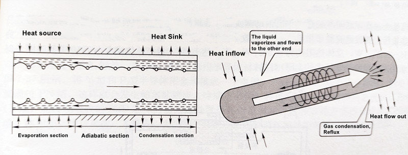
Figure 7-23 Schematic diagram of the working principle of the heat pipe
LED chips are typically directly mounted on top of the heat-absorbing section of the heat pipe, as shown in Figure 7-24. When the heat-absorbing section of the heat pipe is heated, the liquid in the capillary quickly evaporates, and the vapor flows to the other end of the heat pipe, where it releases heat at a slightly lower pressure. It then condenses back into a liquid, which returns to the evaporator section through the action of the porous material capillary. This cycle continues, continually conducting heat away. Adding many metal fins to the heat pipe can enhance convective heat dissipation to the surrounding air.
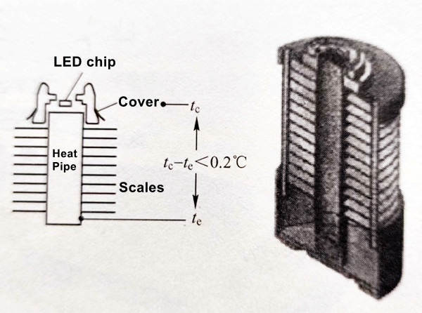
Figure 7-24: LED chips placed on top of the heat-absorbing section of the heat pipe
Under constant conditions, thermal resistance rapidly decreases as the length and diameter of the heat pipe increase, allowing the LED to dissipate heat more effectively. Please refer to Table 7-13 for the heat dissipation performance of heat pipes.
Table 7-13: Heat Dissipation Performance of Heat Pipes
NO.
Heat pipe length/mm
Circle wing diameter/mm
Thermal resistance/(°C / W)
Dissipated power/W
a
50
20
18.8
6.0
b
66
20
14.5
8.0
c
80
20
12.0
10.0
d
110
20
9.9
12.0
e
66
30
10.0
12.0
f
80
30
9.1
13.0
g
110
30
6.6
18.0
h
80
48
5.6
21.5
i
110
48
4.2
28.5
j
110
75
2.9
42.0
(3) Loop Heat Pipe (LHP) Cooling:
A Loop Heat Pipe (LHP) consists of an evaporator and a condenser, and its operating principle is schematically shown in Figure 7-25. The looped pipes transfer the heat from the LED chips to the working fluid inside the evaporator. The working fluid absorbs the heat, evaporates, and then flows towards the condenser. Subsequently, it returns to the evaporator through the capillary action of the porous material in the evaporator. LHPs are effective at transferring heat to distant and easily heat-dissipating areas, providing higher efficiency and flexibility in applications. The thermal resistance of the LHP evaporator is typically between 0.15 and 0.2°C/W, resulting in an overall thermal resistance of approximately 0.5°C/W. LHPs have a lifespan of up to 10 years, and mass production costs are less than $10 USD per unit. Figure 7-26 illustrates an LED luminaire using Loop Heat Pipe technology.
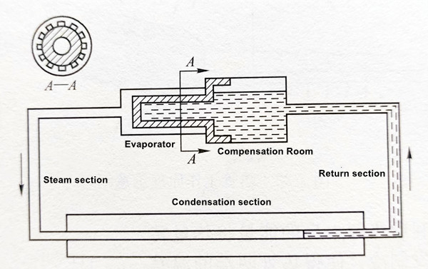
Figure 7-25: Schematic representation of the Loop Heat Pipe principle.
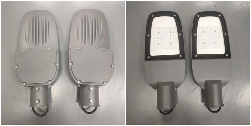
Figure 7-26: LED luminaire employing Loop Heat Pipe cooling.
Active cooling for LED streetlights requires the consumption of additional electrical energy. It is suitable for cooling higher-power LED light sources and provides significantly better cooling performance compared to passive cooling methods. However, it can lead to a reduction in the overall luminaire efficiency.
(1) Heat Sink with Temperature-Controlled Fans:
When LED streetlights have high power levels, passive cooling alone may not dissipate heat quickly enough to keep the LED junction temperature within allowable limits. In such cases, using forced cooling with heat sinks and electric fans is a feasible solution. To meet IP protection requirements, ensure water resistance, and enhance outdoor reliability, integrated heat sinks with enclosures are often used. Temperature-controlled fans are designed based on LED operating temperature, heat sink temperature, and outdoor ambient temperature during different seasons. This approach helps save energy and extends the fan's lifespan. While this cooling solution offers good heat dissipation without polluting the heat sink (as shown in Table 7-14), it has the drawback of finite fan lifespans and additional power consumption.
Table 7-14: Comparison of heat dissipation effectiveness with and without fans.
|
Sample |
Junction |
Luminaire heat sink |
Metal cavity shell |
Room |
Relative to |
|
|
1 |
There is a fan |
69.3 |
59.2 |
46.5 |
29.6 |
39.7 |
|
Fanless |
102.3 |
90.7 |
52.3 |
29.9 |
72.4 |
|
|
2 |
There is a fan |
75.3 |
66.4 |
54.3 |
29.5 |
45.8 |
|
Fanless |
110.1 |
99.7 |
53.6 |
29 |
81.1 |
|
(2) Heat Pipe with Temperature-Controlled Fans:
For LED streetlights with power levels exceeding 200W, a cooling solution that combines heat pipes with finned structures and temperature-controlled fans can reduce the physical size of the heat dissipation design. This approach allows for the use of smaller heat pipes while still achieving effective heat dissipation. However, it shares the same limitation as the previous method: the finite lifespan of cooling fans and additional power consumption.
(3) Semiconductor Refrigeration Cooling:
Semiconductor refrigeration utilizes the Peltier effect in semiconductor materials. Its operating principle, as shown in Figure 7-27, involves connecting N-type and P-type semiconductors with metal to form a thermocouple. When a direct current (DC) power supply is connected, there is an electric current passing through the PN junction, leading to the Peltier effect. The cold end (upper end) absorbs the heat generated by the LED chip, while the hot end (lower end) dissipates the heat absorbed by the cold end through an external heat sink. This cooling solution has the advantages of a simple structure, small size, flexible design, no noise, and no pollution. However, it requires additional electrical energy, affecting system efficiency.
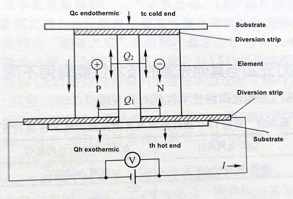
Figure 7-27: Schematic representation of semiconductor refrigeration cooling.
There are other LED streetlight cooling methods available, such as microchannel heat sink cooling and waste heat recovery cooling, which can also be subjects of further research.
Regardless of the cooling method chosen for LED streetlights, it must be seamlessly integrated with the optical design. The cooling solution should not compromise the luminaire's optical performance, and cost considerations must align with user acceptance. Given that LED streetlights are primarily used for roadway illumination with moderate power levels, passive cooling with heat sinks remains a predominant cooling solution.
The choice of LED power and LED arrangement should also be considered from a cooling perspective:
① When selecting individual LEDs, higher power does not necessarily translate to better performance. Higher-power LEDs have much higher chip temperatures during operation compared to lower-power LEDs, leading to more severe light output degradation. For a balance between luminous efficacy and total lumen output, it is advisable to choose LEDs with around 1W of power.
② LED luminaire size is mainly determined by the dimensions of the heat sink. Dense LED arrangements do not necessarily reduce luminaire size; they can increase the complexity of optical design and contribute to glare. Therefore, a distributed arrangement of LEDs is a more reasonable combination.
Contact: Mr. Otis
Phone: +8615815758133
Tel: +8615815758133
Email: Hello@lederlighting.com
Add: No. 1 Gaoxin West Road,High-tech Zone, Jiangmen, Guangdong, China