Welcome: Jiangmen LEDER Lighting Co., Ltd.

Power Factor Correction (PFC) for LED switch-mode power supplies is an electric power technology used to enhance the power factor of the power source in LED lighting systems. Power factor refers to the phase relationship between current and voltage and is used to measure the impact of the power source on the electrical grid load. PFC plays a crucial role in LED lighting systems.
PFC technology for LED switch-mode power supplies can improve the power factor, increase energy efficiency, meet regulatory requirements, and enhance system stability. These advantages make PFC essential in LED lighting systems.
(1) Selection of PFC Inductor L4:
The PFC boost inductor L4 is illustrated in the electrical diagram shown in Figure 7-34. It consists of two windings: WD1, which serves as the main winding for PFC boost, and WD2, which is the bias winding providing a high-frequency voltage source for the VCC pin of U1.
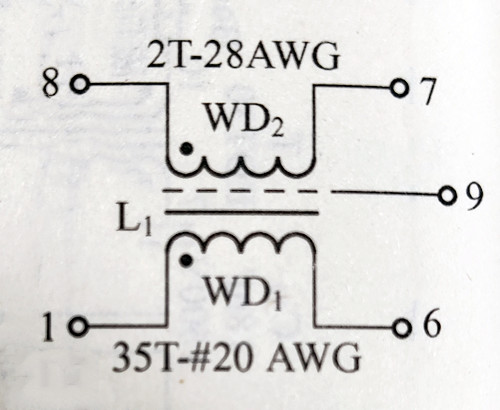
For L4, a TDKPQ32/20 magnetic core with a 12-pin bobbin is used. Figure 7-35 provides a schematic representation of the PFC boost inductor structure.
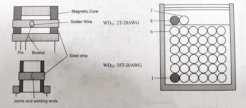
WD1 of L4 is wound using 20AWG (American Wire Gauge, approximately φ0.87mm diameter) insulated magnet wire, starting from pin 1 and winding 35 turns to pin 6. The inductance value at 100kHz and 0.4V is approximately 580uH.
Around the main winding, there is a layer of polyimide film with a width of 7.5mm, followed by winding the bias winding. The bias winding uses 28AWG (approximately φ0.36mm diameter) magnet wire, starting from pin 8 and winding 2 turns to pin 7, and then winding around three layers of 7.5mm-wide polyimide film. A shielding layer made of 6.5mm-wide copper tape (3M150F-1) is applied and connected to pin 9.
(2) Selection of LLC Transformer T:
The electrical diagram of the transformer T used in the LLC resonant converter is shown in Figure 7-36. In this diagram, WD2 represents the primary winding, and WDiA/WDB represents the secondary windings. Figure 7-37 provides a schematic representation of the transformer windings.
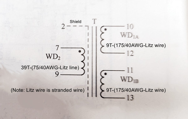
T is selected with an ETD39 magnetic core and an 18-pin bobbin. During the manufacturing process, the secondary winding is wound first using 175 strands of 40AWG twisted wire (approximately φ0.08mm diameter). It starts from pin 10, winding 9 turns, and terminates at pin 12. Then, it starts from pin 11, winding 9 turns, and terminates at pin 13. It is covered with two layers of 10.6mm-wide polyimide film.
The primary winding consists of 75 strands of 40AWG twisted wire. It starts from pin 7, winding 39 turns, and terminates at pin 9. Two layers of polyimide film are applied over the primary winding. The inductance value of the primary winding is 820uH (±10%) at 100kHz and 0.4V, with a leakage inductance of 100uH (±10%). The resonant frequency is ≥700kHz.
The transformer is assembled by inserting two halves of the magnetic core into the bobbin, soldering them together at the seam, and winding a 10mm-wide copper foil around the outside. A copper wire (0.5m) is soldered between the copper foil and pin 2, and the outer side is covered with polyimide film.
The electrical strength of the transformer, from pins 1 to 9 to pins 10 to 18, is rated at AC 3000V (60s, 60Hz).
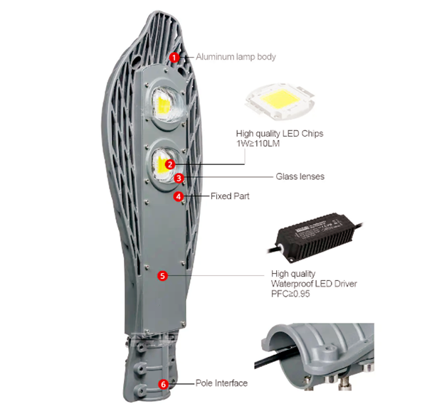
The 200W LED streetlight driver power supply circuit based on LEDER Lighting 's PFC controller FAN6961 and LLC resonant converter controller FSFR100 is shown in Figure 7-38. This offline LED streetlight driver power supply operates with an AC input voltage range of 90-265V and has six outputs, each capable of delivering 0.7A at 48V.
The power supply architecture shown in Figure 7-38 consists of two stages: a PFC stage followed by an LLC resonant half-bridge converter. This two-stage architecture can support significantly higher power compared to a single-stage PFC power supply.
(1) Input Stage Circuit:
In Figure 7-38 (a), VDg4 to VDg7 represent the bridge rectifier LF, and capacitors C14, C5, and the Y2 capacitor C5 connected between the primary side and secondary side ground of the LLC transformer form an EMI filter.
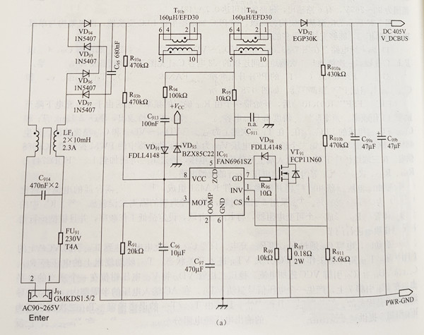
(2) PFC Boost Converter Based on FAN6961 (IC91):
The PFC preregulator, composed of FAN6961 (IC1), T9la/T91b, VD92, and C99a/C99b, is shown in Figure 7-78(a).
After IC1 (FSFR2100) starts, it begins with a frequency determined by R107 and then decreases to the normal operating frequency as C107 discharges. The slope of the frequency reduction is set by the value of C107. The half-bridge output of IC1 drives the LLC network consisting of L101, T1, and C102b and C102a. The voltage on the secondary side of T1 is rectified and filtered by VD201 to VD204 and C201, producing a 48V DC output (VOUT). The second output DC voltage, VDD, powers the PWM controller SG6858 in the LED driver circuit.
The rectified wave voltage at the input of linear regulator IC2, via R202 and other components, is applied to IC3 (FOD2741). IC3 is composed of an optocoupler and a programmable shunt reference element KA431, with the current transfer ratio (CTR) of the optocoupler ranging from 100% to 200%. IC3, in an 8-pin package, is a typical isolated error amplifier. The opto-transistor in IC3 forms a variable resistor with R104 in parallel with R105, setting the minimum operating frequency and adjusting the operating frequency based on the operational conditions.
During startup, capacitor C96 charges via R93a and R93b. As soon as the charging voltage on C96 reaches the startup threshold at IC91's VCC pin, IC91 begins operation, and the PFC switch VT91 enters its switching state. The voltage on auxiliary winding T91a is used to supply current to IC91's VCC pin through R94, C913, and VD91. The voltage on the VCC pin is clamped to an appropriate level by zener diode VD93. A voltage signal at IC91's pin 7 drives VT91. During one-half cycle of the AC input voltage, the conduction time of VT91 is fixed, but the turn-off time varies, determined by the demagnetization of T91a/T91b. The secondary winding T91a also provides zero-crossing detection signal to IC91's pin 5. The 405V output voltage is divided by resistor dividers R901a, R910b, and R97 and fed back to IC1's INV pin. C97 determines the crossover frequency. To achieve a high power factor, the crossover frequency must be below half of the line frequency (50Hz/60Hz).
(3) DC/DC Converter Based on FSFR2100 LLC Resonant Converter:
The DC/DC converter based on the Fairchild PowerSwitch (FPS) FSFR2100 is shown in Figure 7-78(b).
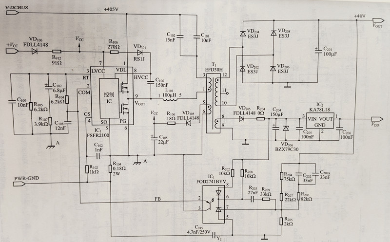
During normal operation, the working current of IC1 is provided by the auxiliary power supply circuit consisting of the bias winding of T1, VD105, R108, and C105. The high-side driver power supply voltage in IC1 is generated by a bootstrap circuit consisting of R106, VD101, and C106.
The current through the middle and lower MOSFETs is measured via R101. The current sensing signal on R101 is filtered through R102 and C102 and fed to IC1's CS pin (Pin 4). IC1's CS pin accepts a negative signal relative to the chip ground. If the voltage on this pin is -0.9V, IC1 will turn off and will only reset when the Vcc voltage on the chip drops below 5V.
(4) LED Constant Current Driver Based on PWM Controller SG6858TZ:
The LED constant current driver based on SG6858TZ is shown in Figure 7-78(c). The outputs of all six LED drivers can deliver up to 0.7A at 48V, resulting in a total output power of approximately 200W.
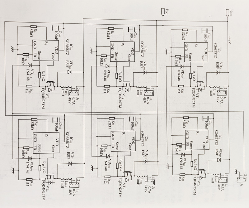
SG6858TZ is a voltage-mode PWM controller available in a 6-pin SOT-26 or 8-pin DIP package. It has a startup current of 9uA and operates with a working current of 3mA. It offers constant output power limiting, current limiting on a per-cycle basis, and short-circuit protection within the universal AC input range of 90-264V. To protect the external power MOSFET, SG6858TZ's output driver is clamped at 17V.
In the LED constant current driver based on SG6858TZ (IC92IC97), a current is detected through the inductors (L102L107) using resistors (R13R16, R17, and R22), and the current sensing signal is fed to the Sense pin of SG6858TZ. SG6858TZ can maintain a constant peak inductor current, thus keeping the output current constant. Resistors R7R9 and R17, R20, R23 set the operating frequency of the LED driver, while resistors R10~R12, R18, R21, and R25 set the current sensing levels. To reduce the output current from 700mA to 350mA, the resistance values of the current sensing resistors should be doubled.
A low-frequency PWM signal of approximately 200Hz is applied to J7 for dimming the LEDs.
Today's release of the LED street light driver PFC article contains a relatively high level of professional knowledge, which may not be easily understood by everyone. This article was compiled by our electronic engineering team based on many years of experience, and it is written in a clear and accessible manner, showcasing our team's significant expertise. If you have any questions or concerns, please do not hesitate to contact me. I will be more than happy to provide you with answers. During the consultation, you can also assess the professionalism of our team and the quality of our service.
Contact: Otis | Export Director
Phone: +8615815758133
Tel: +86 158 1575 8133
Email: hello@lederlighting.com
Add: No. 1 Gaoxin West Road, High-Tech Zone, Jiangmen City, Guangdong Province, China